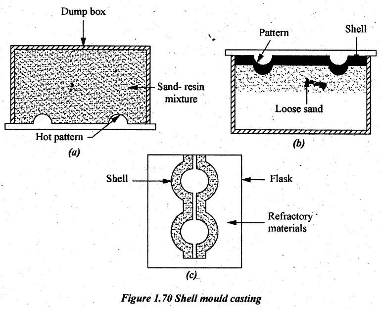
1. Shell Mould Casting
The shell mould casting is a semi-precise method for producing small castings in large numbers. The process involves the use of a match plate pattern similar to cope and drag patterns which are used in green sand mould casting.
Initially, the patterns are machined from copper alloys, aluminium or cast iron depending upon the lift of the pattern. They are made with usual allowances and polished surfaces. Then, it is attached to the metal match plate.
The mould material contains 5 to 10% of phenolic resin mixed with fine dry silica. These are mixed with either dry oil or alcohol. It should be noted that there is no water used.
The pattern is heated to 230-600°C. Then, the sand-resin mixture is either dumped or blown over its surface. Sometimes, to prevent the sticking of sand with pattern, a release agent silicone is sprayed over the hot pattern. The heated pattern melts and hardens the resin. It results in bonding the sand grains closely together and forms a shell around the pattern. After a specified time of 20-30 sec, the pattern and sand are inverted as shown in Figure 1.70(b). The thickness of the shell can be accurately controlled by the time of contact of the mixture with the heated pattern. In about 20-30 sec, a normal shell thickness of 6 mm can be obtained. The extra sand which is not adhered to the shell is removed off. The thickness of the shell is depending on the required strength and rigidity to hold the weight of the liquid metal to be poured into the mould.
Then, the mould is heated in an oven at 300°C for 15-60 sec. This curing makes the shell rigid when it can be stripped off by means of ejector pins mounted on the pattern. Thus, the formed shell constitutes one-half of the mould. Two such halves placed one over the other make the complete mould as shown is Figure 1.70 (c).
While pouring the molten metal, the two halves are clamped down together by clamps or springs. After cooling and solidification, the shells are broken or shaken away from the castings.
Applications:
1. It is used for making brake drums and bushings.
2. Cams, cam shaft, piston and piston rings can be made.
3. It is used for making small pulleys, motor housing, fan blades etc.
4. Air compressor reservoir and cylinders, crankcases, conveyor, rollers etc., can be made.
Advantages:
1. A high accuracy castings with tolerances of ± 0.002 to 0.005mm/mm is possible.
2. Good surface finish can be obtained.
3. Complex parts can be made by this method.
4. Less sand is used compared to other methods.
5. Moulds can be stored for long time.
6. Permeability of thin shell moulds is high. Therefore, defects are less. Better quality castings can be made.
Limitations:
1. Only small size of the castings can be made.
2. Serious dust and fume problem during sand and resin mixing will occur.
3. The cost is more.
4. Carbon pickup may occur in the case of steels.
2. Investment Casting or Lost Wax Process
The castings obtained by this method have very smooth surfaces and possesses high dimensional accuracy. Hence, it is called precision investment casting. Here, the term “Investment” means the layer of refractory material with which the pattern is covered to make the mould. Similar to sand casting method, the mould cannot be used again and again.
The method involves the use of disposable pattern made of wax surrounded with a shell of refractory material (i.e. ceramic) to form the casting mould. Once the refractory material is hardened, its internal geometry takes the shape of the casting. The wax is melted out and molten metal is poured into the cavity where the wax pattern was. The metal solidifies within the ceramic mould and then the metal casting is broken out. This method is also called “Lost- wax method' since the pattern made of wax is melted out and gets destroyed.
Various steps involved in lost wax process:
1. The master pattern is prepared by casting process. It may be made of brass, aluminium alloy or steel. The dimension of the pattern is slightly larger than the actual size of the part to be made to compensate the adjustments in the die, wax, in the investment material, and casting material.
2. A composite die is used for making master pattern. The die is made of low-melting alloy such as bismuth alloys, aluminium, cast iron etc. Master pattern die cavity is formed by machining process. Generally, split type cavities are formed.
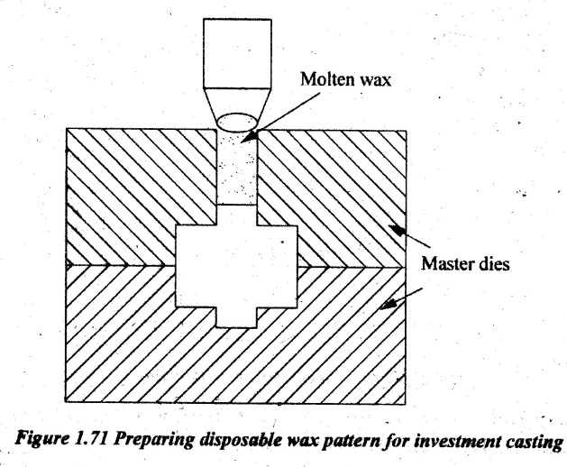
3. First, halves of die cavities are clamped together. Molten wax is injected under the pressure of about 4 bars to the die cavity. If it is a plastic material such as polystyrene, polythenes etc., the injection pressure is in the order of 35 bar with high temperature. Die cavities are preheated to avoid immediate solidification of wax or plastics. If it is not preheated, partial filling of die cavity takes place. This disposable pattern is rinsed in alcohol to remove grease and dirt.
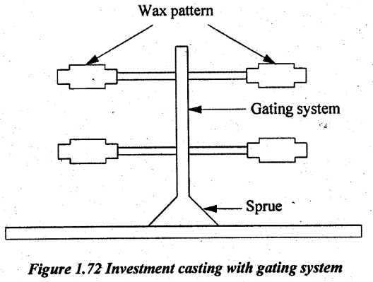
4. If the size of wax pattern is large, the several 'small wax patterns are first prepared and assembled together with a gating system along with central sprue. Assembling various small wax patterns are welded by using heated tools known as cluster. One such cluster is shown in Figure 1.72
5. The assembled wax patterns have to be smoothened /super finished before putting into operation. It is done in the following two stages:
Stage 1:
First, slurry is made by mixing fine silica either with water or ethyl silicate. Then wax patterns are dipped in this prepared slurry to give the primary coating of 1 mm thickness. It provides the improved surface quality to wax patterns. Then wax patterns are dried.
Stage 2:
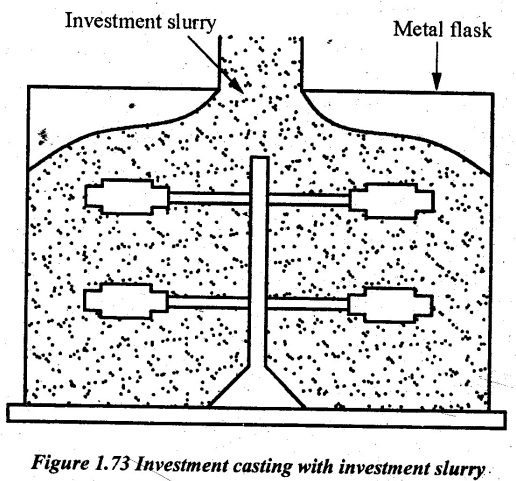
In this stage, ceramic slurry is first prepared by using refractory material such as silica or zirconia and binder such as gypsum. The gypsum is purely water-based sodium silicate. Wax is a solid type mould placed over the assembled wax patterns. Then, the ceramic slurry is poured over these assembled patterns as shown in Figure 1.73.
Then, the pattern is taken out of the slurry and rotated to produce a uniform coating, to fill inside corners and to drain out the excessive slurry. Finally, fine-grain silica sand is sprinkled over the wet slurry surface.
6. After applying coating, the mould is prepared using assembled wax patterns. Next, the mould is made along with wax patterns dried in air for about 2 to 3 hours. Then baking of patterns is done in an oven for 2 hours for melting the wax patterns. When the heating temperature reaches about 100 to 120°C, the wax will start to melt. Finally, the melted wax will flow out through the sprue in molten form.
7. Again, the entire mould is transferred to the heating furnace. First, the mould is held at 150°C for further drying. Next, the heating is continued about 800 to 900°C to vapourize remaining wax inside the mould cavity.
8. The liquid metal is poured into this mould still it is hot. The preheated mould ensures that the molten metal completely fills the cavity and also saves the liquid metal from acquiring the moisture. It avoids high thermal gradient between liquid metal and mould. In some cases, the pouring is conducted in a vacuum chamber or in a protective inert atmosphere. Then, it is allowed to solidify by cooling.
9. After the solidification is over, the castings are removed from the mould by shaking out. At that time, the fragile material of mould will break. Then, gates and sprue called runner are removed usually by machining.
10. Finally, the adhered investment material is removed from the casting surface by sand blasting or tumbling operation. Then the castings are inspected to detect casting defects.
Applications:
1. Production of nozzles, buckets, vanes and blades for gas turbine.
2. Making parts for aerospace industry such as aircraft enghes, frames and fuel systems.
3. This process is applied in costume jewellery.
4. Rock drill thread chaser holder blocks are produced by this method.
5. Parts for producing machine tools and accessories, scientific instruments and sewing machines.
6. Small parts such as reciprocating slides for cloth cutting machines, movie camera parts etc., are produced by this method.
Advantages:
1. Complex shapes can be cast accurately.
2. Surface finish is very good.
3. High accuracy can be maintained.
4. Number of casting can be made at a time.
5. Undercut and other intricate shapes which would not allow the withdrawal of a normal pattern are easily obtained.
6. Unmachinable alloys can be cast.
Limitations:
1. Only small size of the casting can be made.
2. This process is more expensive.
3. Location of holes is impossible.
3. Ceramic Mould Casting
In this method, the ceramic slurry is first prepared by mixing fine grained refractory powders of zircon (ZrSiO4), alumina (Al2O3), fused silica (SiO2) and patented bending agents.
Then, this slurry is applied over the pattern surfaces to form thin coating around it. After applying the coating on the pattern, it is baked in a less expensive fire clay. After this, the pattern is removed out from the mould and it is transferred to an oven for further heating mould about 1000°C. Then, the molten metal is poured into the mould cavity through the sprue to produce castings. In this case also, the preheated mould is used during pouring of molten metal. As a result, the partial filling of moulding is completely eliminated due to solidification of molten metal. This type of mould casting method is mainly used for all materials using better ingredients in slurry.
4. Pressure Die Casting
In the previous casting processes, disposable moulds are used where it must be broken in order to obtain the castings. In the die casting process, the mould, called a die, is used for making a casting which is permanent. In this process, the molten metal is forced into the mould cavity under high pressure. The process is used for casting a low melting temperature material, e.g. Aluminium and Zinc alloys, brass etc. The die-casting is carried out as follows:
1. The molten metal is forced under pressure into the assembled die.
2. The die is water-cooled. So, the molten metal cools down and immediately becomes solid.
3. The die is opened. Then, the finished casting is ejected by pins.
The mould, normally called die, is made in two halves in which one is fixed and the other one is movable. Medium carbon and low alloy tool steel are the most common die materials. There are two types of die casting processes. They are:
1. Hot chamber die casting
2. Cold chamber die casting
1. Hot chamber die-casting:
In hot chamber die-casting, the melting furnace is an integral part of the mould. There is a gooseneck vessel which is submerged in molten metal. There is a plunger at the top of the gooseneck vessel as shown in Figure 1.74. When the plunger is in the upward position, the molten metal will flow into the vessel through a port provided on the sidewall.
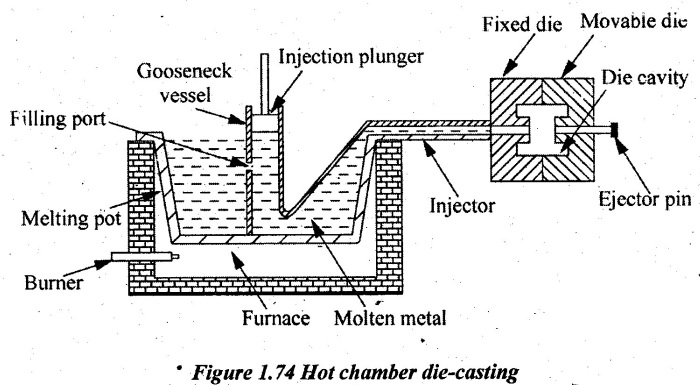
When the plunger comes down, the molten metal is forced into the dies. Since, the die is immediately cooled by water and sufficient cooling is provided for solidification. Then, the movable die is moved some distance and finished casting is removed by ejectors. The plunger and movable die are operated by hydraulic systems. The operating pressure of hydraulic plunger is 15 MN/m2.
Hot chamber die-casting is suitable for casting of metals such as Zinc, tin and lead.
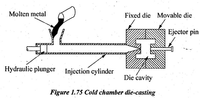
2. Cold chamber die-casting:
In cold chamber die-casting, the metal melting unit is not an integral part of the machine. The metal is melted in a separate furnace and brought to the machine for pouring. The process is shown in Figure 1.75.
The machine has a cold chamber of cylindrical shape with a hydraulic plunger. A measured quantity of molten metal is poured into the injection cylinder. Then the plunger moves to the right and forces the molten metal into the die cavity. As the die is water-cooled, immediate solidification of molten metal will take place. Then, the dies are separated. The finished casting is removed by an ejector pin.
Applications:
Pressure die casting is used for making flowing equipment / components:
1. Household equipment such as washing machine parts, vacuum cleaner body, fan case, store parts etc.
2. Automobile parts such as fuel pump, carburetor body, horn, wiper and crank case.
3. Components for telephones, television sets, speakers, microphones, record players and soon
4. Toys, such as pistols, electric trains, model aircraft's etc.
Advantages:
1. Very accurate castings of can be produced with the dimensional tolerance range of ± 0.03 to 0.25 mm.
2. Castings with very good surface finish can be made.
3. Rate of production (700 castings per hour) is high.
4. Castings with varying thickness wall can be made.
5. There is no possibility of sand inclusions.
6. Cored holes down to 0.75 mm diameter at accurate locations are possible.
7. Casting defects are less.
8. It can be stored and used for long time.
9. Die has long life. Approximately 75,000 castings can be produced using a single die in its life period.
10. The sprue, runners and gates can be remelted. Hence, the scrap loss is less.
Limitations:
1. Only small parts can be made.
2. Only non-ferrous metals can be cast.
3. Equipment cost is high.
4. It is more suitable for mass production only.
5. Gravity Die Casting
Gravity die casting is also called permanent mould casting. The mould is generally made of two halves. They are hinged at one end. There is a provision for clamping them together at the other end. A permanent mould is necessary for producing large number of casting of similar shape. A permanent mould is made of heat resisting cast iron, alloy steel, graphite or other suitable material.
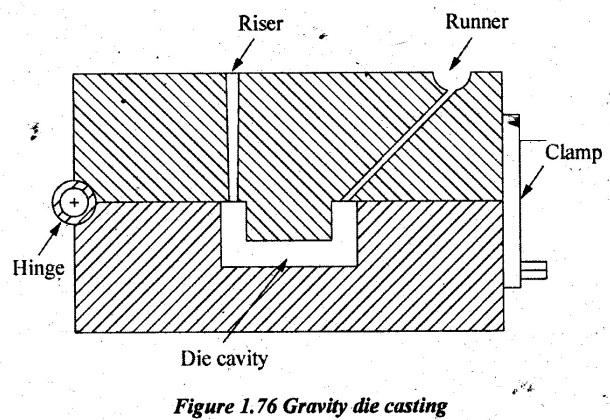
Pouring cup, sprue, gates and riser are made in this mould itself. First, the mould is preheated. Then refractory coating is done by spraying or brushing. This coating protects mould surfaces from erosion and sticking. Lubricating casting may also be given for easy removal or castings.
The molten metal is fed into the mould with the help of gravitational force. Hence, this process is called gravity die-casting. After the solidification, the casting is removed by opening the top die.
Almost all metals can be cast in this mould. Non-ferrous materials, such as zinc, copper, aluminum, lead, magnesium and tin alloys are most often cast in this method.
This method is suitable only for making components of simple shapes and design, and uniform wall thickness.
Applications:
It is used for carburetor bodies, oil pump bodies, pistons, connecting rods, gear covers etc.
Advantages:
1. Accurate casting can be made.
2. It gives good surface finish to castings.
3. It is more suitable for mass production.
4. Wastage and rejection of metal is less.
5. Less floor space is enough.
6. Production rate is high.
7. Production cost is less.
8. Castings are free from defects.
Limitations:
1. Only small castings can be made.
2. It is only suitable for mass production.
3. Initial cast is more.
4. Complicated shaped castings cannot be produced easily.
5. The removal of casting from the mould is difficult.
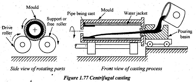
6. Centrifugal Casting
Centrifugal casting is primarily used for making hollow castings such as pipe without using core. In this process, a metal mould is made to rotate. The rotating mould is mounted on a trolley as shown in Figure 1.77. The trolley moves over rails. The end of the mould is closed by end cores to prevent the flow of metal out of the mould.
The metal is poured into the mould through a long spout. The mould is rotated by an electric motor or mechanical means as well as it moves axially on the rails. Due to centrifugal force, the molten metal is thrown to the walls of the mould. The outside of the mould is water-cooled. So, the molten metal immediately solidifies. The centrifugal casting method is. used for producing cylindrical and symmetrical objects.
Applications:
Components such as water pipes, gears, bush bearings, fly wheels, piston rings, brake drums, gun barrels etc. can be made using this process.
Advantages:
1. Core is not required to produce hollow components.
2. Rate of production is high.
3. Pattern, runner and riser are not required.
4. Impurities in the metal are driven out. Therefore, defects in castings are very less.
5. Thin castings can be made...
6. Castings have uniform physical properties.
Limitations:
1. It is suitable only for cylindrical and symmetrical shaped castings.
2. The cost of equipment is high.
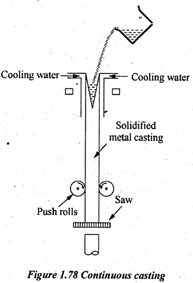
7. Continuous Casting Process
In this process, molten metal is poured from a laddle continuously into a long vertical mould. The mould is made of copper, brass or graphite. The mould is water-cooled. Hence, the molten metal is immediately solidified. This solidified casting comes down continuously.
Saw or oxy-acetylene flame is used to cut the casting of required length. X-ray unit controls the pouring rate of molten metal from the laddle. Since, the molten metal is flowing from the bottom surface, there will not be any impurities in castings. Lubricating oil is applied between casting and mould wall to reduce friction. The guide rolls at the bottom keep on pulling the casting to match with the cooling rate. Argon gas is supplied at the top of the mould to prevent atmospheric reaction with the molten metal. By controlling the cooling rate, the grain size and structure of metal can be regulated.
Applications:
It is used to produce rods, pipes, slabs, ingots, bars etc.
Advantages:
1. The rate of production is high.
2. Good surface finish can be obtained.
3. There are no impurities on the castings. Segregation on castings is reduced.
4. Grain size and structure can be regulated by controlling the cooling rate.
5. The process can be automated. Hence, the labour cost can be reduced.
Limitations:
1. The cost of mould and other equipment is high.
2. The operation and maintenance of the equipment are costlier.
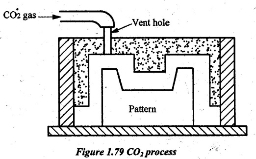
8. Carbon Dioxide (CO2) Process
Carbon dioxide moulding is a sand casting process that employs a moulding mixture of sand and liquid silicate binder such as sodium silicate (Na2SiO3). The moulding mixture is then hardened by blowing carbon dioxide (CO2) gas through it. For this reason, the process is commonly known as CO2 process.
In this process, CO2 gas forms a weak acid which hydrolyzes the sodium silicate. Thus, an amorphous silica is formed and it becomes the bond. There is also a bonding action from the sodium silicate itself. The use of CO2 gives an almost instantaneous set. Mould is fully hardened before the pattern is drawn from mould sections.
It reduces the production time as well as the fuel cost. It also reduces the number of mould boxes required for making moulds. This process also offers a great deal of accuracy in production.
Steps involved in CO2 process:
1. Suitable proportions of silica sand and sodium silicate binder (3-5% based on sand weight) are mixed together to prepare the sand mixture.
2. Additives such as aluminium oxide, molasses etc., are added to impart the favorable properties and improve the collapsibility of the sand.
3. The pattern is placed on a flat surface with the drag box enclosing it. Parting sand is sprinkled on the pattern surface to avoid sand mixture sticking to the pattern.
4. The drag box is filled with the sand mixture and rammed manually till its top surface. Rest of the operations such as placing sprue, riser pin and ramming the cope box are similar to green sand moulding process.
5. At this stage, the carbon dioxide gas is passed through the vent holes as shown in Figure 1.79 for a few seconds.
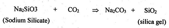
6. Sodium silicate reacts with carbon dioxide gas to form silica gel that binds the sand particles together. The chemical reaction is given by
7. The sprue, riser and the pattern are withdrawn from the mould and gates are cut in the usual manner. The mould cavity is finished and made ready for pouring.
Applications:
It is ideally used for casting applications where the speed and flexibility are paramount.
Advantages:
1. Good dimensional accuracy can be obtained through strong cold mould.
2. Excellent surface finish can be obtained.
3. It is generally used for high-production runs.
4. It accommodates a wide range of core and mould sizes.
5. When used for making cores, CO2 process can be automated for large production and speedy production runs.
6. All sands can be used as a base aggregate for silicate sand mixture.
7. Less gas evolution occurs during pouring of molten metal and hence, it leads to casting defects.
8. It ensure instantaneous strength development. The development of strength takes place immediately after carbon dioxide gassing is completed.
Limitations:
1. Poor collapsibility of moulds is a major disadvantage of this process.
2. There is a significant loss in the strength and hardness of moulds which have been stored for extended period of time.
3. Over gassing and under gassing adversely affect the properties of cured sand.
4. More alkaline is the binder, longer it takes to gas and greater will be the tendency for the core to remain rubbery instead of firm.
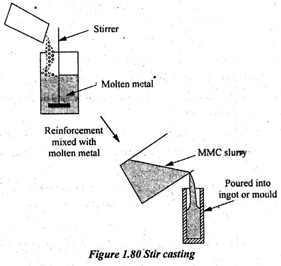
9. Stir Casting
Stir casting is a liquid state method of composite materials fabrication in which a dispersed phase (ceramic particles, short fibers) is mixed with a molten matrix metal by means of mechanical stirring. Among the variety of manufacturing processes available for discontinuous metal matrix composites, stir casting is generally accepted and currently practiced commercially.
Process of stir casting:
(a) In general, stir casting of MMCs (Metal Matrix Composites) involves in producing a melt of the selected matrix material, followed by the introduction of a reinforcing material into the melt and obtaining a suitable dispersion through stirring.
(b) The next step is the solidification of the melt containing suspended particles to obtain the desired distribution of the dispersed phase in the cast matrix. The schematic diagram of this process is as shown in Figure 1.80.
(c) In composites produced by this method, particle distribution changes significantly. It depends on process parameters during both melting and solidification stages of the process.
(d) The addition of particles to the melt drastically changes the viscosity of the melt and it has implications for casting processes. It is important that solidification occurs before appreciable settling is allowed to take place.
Advantages:
(a) Its advantages lie in its simplicity, flexibility and applicability to large scale production because in principle it allows a conventional metal processing route to be used and its cost is low.
(b) This liquid metallurgy technique is the most economical of all available routes for metal matrix composite production. This method allows very large sized components to be fabricated. It is able to sustain high productivity rates.
(c) The cost of preparing composites materials using a casting method is about one-third to one-half of a competitive method. For high volume production, there shall be a possibility for further reduction of cost to the extent of one-tenth
No comments:
Post a Comment