Tuesday, December 26, 2023

FRICTION STIR WELDING


Introduction 

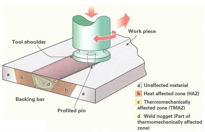
Friction stir welding (FSW) is a solid-state joining process developed at TWI Ltd in 1991. FSW works by using a non-consumable tool, which is rotated and plunged into the interface of two workpieces. The tool is then moved through the interface and the frictional heat causes the material to heat and soften. The rotating tool then mechanically mixes the softened material to produce a solid-state bond. The FSW process is illustrated in Figure 1.

Figure 1. Friction Stir Welding process

Applications

FSW is mainly used in industry to join aluminium alloys of all grades, in cast, rolled or extruded condition. Aluminium alloy butt joints with a thickness from 0.3mm to 75mm have been successfully joined in a single pass (dependent on workpiece material, machine power and structural stiffness). Other materials have also been successfully joined, namely magnesium, titanium, copper, and steel alloys. Plastics and metal matrix composites (MMC) have been explored. Dissimilar combinations between these materials have also proven possible.

Since its invention, FSW has become a proven technology in most manufacturing sectors. Some of its known applications include:

Shipbuilding and Marine

  • panels for decks, sides, bulkheads and floors
  • hulls and superstructures
  • helicopter landing platforms
  • masts and booms

Aerospace

  • fuselage and wing structures
  • fuel tanks for space vehicles

Railway industry

  • rail stock vehicle floor, side and roof panels, namely for high-speed trains
  • railway tankers

Automotive

  • battery trays
  • invertors
  • engine chassis cradles
  • wheel rims
  • tailor welded blanks
  • car body structures
  • seat frames

Electronics

  • enclosures for circuits
  • cooling and thermal management plates
  • Apple’s iMac computer body
Figure 2. Friction stir welding applications
Figure 2. Friction stir welding applications: (a) wheel rim, (b) joining of aluminium extrusions, and (c) space propellant tank

Microstructure and Mechanical Properties

Friction stir welds typically exhibit three main microstructural regions: a weld nugget, a thermo-mechanically affected zone (TMAZ) and a heat-affected zone (HAZ). Technically, the weld nugget and TMAZ are both “thermo-mechanically affected zones,” but are considered separately for exhibiting distinct microstructural features. The weld nugget experiences dynamic recrystallisation while the TMAZ does not. The extent and microstructural composition of these zones are dependent on the material and processing conditions (parameters and tool design, for example). Figure 1 provides an illustration of these zones.

With regards to the mechanical properties of friction stir welded aluminium alloys, it is now well established that they are generally superior to those obtained by arc welding processes.

There are two main standards that describe the guidelines for use:

AWS D17.3/D17.3M 2021 “Specification for Friction Stir Welding of Aluminum Alloys for Aerospace Applications”

And

ISO 25239:2020 Friction stir welding — Aluminium

 process.

Advantages

Friction stir welding offers many advantages over fusion-based joining processes, especially when joining aluminium alloys:

  • Remaining in the solid-state, avoiding many of the defects associated with melting and solidification during fusion welding, such as pores and solidification cracks.
  • The peak temperatures are lower, allowing a reduction in distortion and shrinkage.
  • Being able to join many ‘non-weldable’ aluminium alloys, namely from the 2xxx and 7xxx series.
  • Producing superior mechanical properties.
  • No filler metals, flux or shielding gas are required. No fumes, porosity or spatter are generated.
  • Fully automated, making the process highly repeatable.
  • Energy efficient.
  • Does not require special edge preparation in most applications. 

Friction Stir Welding (FSW) – Process & Applications


Friction stir welding (FSW) was first introduced in 1991. This is a solid-state process of joining two parts. In this process, the metal parts do not melt. Instead, welding friction between the metal parts and the FSW tool creates heat which allows the atoms of the two metal parts in order to fuse.

FSW, nowadays, is widely used for welding aluminum alloys and also other metal or metal alloy parts. FSW can be used to join parts made of the same metal as well as two different metal parts.

Process of FSW

The ‘tool’ of FSW is the most important part of the process. It is cylindrical and has a probe (a pin with a diameter smaller than the tool shoulder). The step-by-step process is:

Friction stir welding process

  1. Firstly, two metal workpieces are kept in the friction stir welding machine side by side in order to make a butt joint.
  2. The tool then rotates and goes into the two clamped workpieces.
  3. The tool creates a hole in the middle of the joint and penetrates long enough so that the tool shoulder can touch the surface of the workpieces.
  4. After that, the tool dwells for a short time and then starts to move forward.
  5. The welding friction between the wear-resistant tool and the job parts creates heat. which makes the metal soft but doesn’t melt the metal.
  6. Dynamic recrystallization occurs on the workpiece material which causes severe solid-state deformation and attaches the two workpieces at a microstructural level.

This is how the whole friction stir welding process works.

Friction Stir Welding Tool Design

Various tools for FSW

Designing the tool is very important because the welding speed and quality depend on the tool. Some important facts/criteria for the FSW tool are:

  • The tool should be tough, strong, and have a melting point temperature high enough to withstand the welding temperature.
  • The thermal conductivity of the tool should be very low so that no heat loss occurs.
  • Tool Steel (AISI H13) is perfect for friction stir welding of alloys of aluminum whose thickness ranges from 0.5 to 50 mm.
  • ‘Whorl’ design friction stir welding tools have variable pitch thread. It uses a tapered pin that has re-entrant features. This design improves the material’s downward flow.
  • Triflute design (three tapering systems) improves the movement of material around the tool.
  • Trivex tool design is simpler. During welding, this design helps to lower the forces that act on the tool.
  • The concave shoulder profile design of the tool helps to reduce scrap and maintain downward pressure.

FSW Tool Speeds

There are two types of speed for the FSW tool such as rotational and translational speed. It is very important to choose these speed parameters carefully in order to make the welding cycle more efficient.

The workpiece material should be hot enough so that less force is required in order to make the bond. Faster rotation and slower translation of the tool will result in high heat production.

If the material is too cold or too hot, there will be defects in the final part. So, the heat should be at an optimum level. To reach that optimum level, the rotational and the translational speed should be optimized.

Applications of FSW

FSW welding is widely used in many industries for joining various metal components. The following industries use friction stir welding for its benefits:

Automotive Industry

Many components in the automobile industry such as motors, battery pack boxes, automobile engine frames, DC/DC converter, airbag inflator, etc. require FSW. Fully loaded airbag inflators can easily be welded due to the narrow heat-affected zone of FSW welding.

Network and Communication Industry

Various telecommunication device parts, 5G communication components, etc. requires friction stir welding for joining two parts. Many friction stir welding companies around the world make parts for this industry.

Aerospace Industry

In the aerospace industry, a low compression rotor is joined with a tube using the friction stir welding process. Cluster gear and many other components in this industry also require friction stir welding.

Applications of FSW

Marine Industry

Many large and small projects in the Marine industry use friction stir welding to speed up the construction. This saves a lot of time as well as increases the profit. Some examples where FSW is needed in this industry are flooring, deck, bridges, seawalls, panels, bulkheads, walkways, etc.

Agricultural industry

Many components in the agricultural industry such as water pumps, water pump gear, diesel engines, etc. need FSW. The friction stir welding companies can reduce the costs of agricultural components significantly for the agricultural industry.


Sunrise Metal – Friction Stir Welding Parts Manufacturer in China

Sunrise metal is one of the top friction stir welding suppliers and parts manufacturers in China. We provide friction stir welding services for many industries such as automotive, aerospace, marine, telecommunication, etc. Our goal is to achieve customer satisfaction by providing a one-stop solution for FSW welding parts.

Sunrise Metal’s friction stir welding services include:

Part Design and Development

We have experts in our team who have decade-long experience in this field. They always work to develop the parts for our clients and also design new parts from scratch if necessary. Our clients can rely on our team without worrying about the quality of the design or the parts.

FSW Parts Manufacturing

Our facilities own one of the advanced friction stir welding machines of this era, the TS-1260. This machine is capable of precisely joining the same and different types of metals. We use this to make FSW parts for our clients.

Friction stir welding machine in Sunrise Metal

Die Casting

If our client requires, we can manufacture the metal FSW workpiece part by part using modern semi-solid die casting, high pressure die casting, vacuum casting, etc. processes. Then we can join the parts using the FSW process which makes the final component very strong and reliable.

Finishing Operations

Aside from the above services, we also provide surface finishing services for the finished parts. We do this to make the parts corrosion resistive, stronger, and long-lasting.

So, these are our friction stir welding services. As you can see, we provide different services so this saves a lot of costs. Our clients are happy to take our services because we always focus on the quality as well as on-time delivery. For this reason, Sunrise metal is one of China’s top friction stir welding suppliers.


What Are Some Common Features of FSW?

Following are the features of the FSW welding process:

  • Friction stir welded parts show better mechanical properties. For example, friction stir welding aluminum alloy parts have better mechanical properties than arc welding aluminum parts.
  • FSW parts mainly have three microstructural regions such as heat-affected zone (HAZ), thermomechanical affected zone (TMAZ), flow arm zone, and weld nugget or stir zone.
  • The tool shoulder pulls some material from the upper surface of the weld part at the time of welding. This zone is known as the flow arm zone.
  • Dynamic crystallization occurs in the weld nugget zone but does not occur in the thermomechanical affected zone.
  • The HAZ zone of FSW parts is similar to other types of welded parts. This zone is affected by the friction heat but does not deform.
  • The TMAZ zone appears on both sides of the weld nugget. Unlike weld nugget, its microstructure is recognizable.

What are the Advantages of the FSW Process?

There are many friction stir welding advantages, for example:

Friction stir welding Parts advantages-

  • The low-temperature results in less distortion and shrinkage of parts. So, the part dimensions are more accurate.
  • FSW parts are highly defect-free. Defects such as solidification crack, porosity, or hot crack do not occur in these parts.
  • FSW is environmentally friendly as it doesn’t produce any UV radiation, spatter, or fumes.
  • For the friction stir welding of aluminum alloys, it is not mandatory to have any shielding gas, flux, or filler materials.
  • The friction stir welding process is very energy efficient.
  • It is easy to make this process automatic using the latest machine tool technology which reduces the labor cost.
  • FSW parts do not require any expensive machining after welding.
  • This process is suitable for joining many 2000 and 7000 series aluminum alloys that are not weldable by other welding processes.

So, these are the most significant friction stir welding advantages.

What Materials Can Be Welded Using the Friction Stir Welding Process?

The friction stir welding process is suitable for various materials. For example,

Aluminum

Before the invention of friction stir welding, some grades of aluminum were not weldable, for example, the 2000 series and the 7000 series aluminum. So, FSW was invented for these grades of aluminum and its alloys. Friction stir welding aluminum parts exhibits much better mechanical properties than other types of welding aluminum parts.

Copper and Its Alloys

Copper has high electrical and thermal conductivity. For this reason, it was very difficult to weld copper parts. But with the invention of FSW, it has become very easy to weld copper and its alloys.

Magnesium

It was very difficult to carry out the welding process of magnesium using fusion techniques. FSW helped to overcome this difficulty and now magnesium parts can easily be welded with FSW welding.

Steel and Ferrous Alloys

Friction stir welding of ferrous alloy and steel helps to reduce the rectification costs as well as distortion. FSW Steel parts have fewer defects which are economical for production.

Titanium

Other types of welding processes can be applied to titanium parts. But the problem occurs when there is a poor weld quality or workpiece distortion. FSW shows no such problem and is the best option for welding titanium parts.

Hafnium and Zirconium

Various industries such as power generation, oil refining, and petrochemical industries use these two metals. In these industries, FSW helps to join parts made of hafnium or zirconium easily and effectively.

Why Friction Stir Welding is Known as a Green Technology?

There are many reasons why friction stir welding is known as a green technology. The most significant reasons are:

  • There is no requirement of shielding gas in order to weld low melting point temperature materials in FSW.
  • FSW eliminates grinding wastes.
  • The requirement for cleaning weld surfaces is very mild in FSW.
  • FSW does not require degreasing so there is no need for any solvents.
  • There is no occurrence of harmful emissions in the friction stir welding process.

To sum it up, FSW doesn’t provide any negative impact on the environment by emitting harmful gases or by any other means. For this reason, it is green technology.

What Are the Differences between Friction Stir Welding and Fusion Welding?

Fusion welding is the general term for different welding processes such as SMAW, GTAW, MIG welding, etc. The below table shows the differences between Friction Stir Welding and Fusion Welding:

Friction Stir WeldingFusion Welding
This is a solid-state welding process.This is a liquid-state welding process.
Here, the workpiece material doesn’t melt.The workpiece material melts in this process.
2000 and 7000 series aluminum alloys are weldable with this process.2000 and 7000 series aluminum alloys are not weldable with this process.
The friction between the workpiece and the FSW tool produces heat for welding.Electricity or other sources of power produces heat for welding.
This is cheaper than fusion welding.This is costlier than friction stir welding.
The weld quality is better than fusion welding.The weld quality is not so good as friction stir welding.
This is more eco-friendly than fusion welding.This is less echo-friendly than friction stir welding.


What are the Differences between Friction Welding (FRW) and Friction Stir Welding (FSW)?

When it comes to friction stir welding vs friction welding, there are a few differences. The below table shows these differences:

Friction Stir WeldingFriction Welding
Here an FSW tool is used which has a probe and a shoulder.No tool is used in this process.
The friction occurs between the tool and the workpieces.The friction occurs between the two workpieces.
Here the tool rotates and then moves along the joint axis to create the friction and heat to join the two parts.Here the two workpieces (face to face) move up and down which creates friction and also heat between the surfaces.
This process produces heat-affected zones (HAZ).This process does not produce heat-affected zones (HAZ).
Complex shapes are weldable with this process.There are some limitations in welding complex parts with this process.

In short, it can be said that the FSW process is more advanced than the FRW process.

Beamed Energy Propulsion Vehicles

 Summary

Izentis is a world leader in beamed energy propulsion technology. Our team has experience in both the theoretical and experimental aspects of the technology. This includes publishing papers on heat exchanger technology and building test rocket vehicles. The concept of beamed energy propulsion is to use an external energy source such as a ground-based laser or microwave to power a rocket. This removes the energy limitation of chemical rockets allowing for both high thrust and high specific impulse. Such technology could allow for single-stage-to-orbit launch vehicles with significant structural margins, enabling “jetliner-like” re-usability. A fully re-usable launch vehicle could yield launch costs well below $100/pound, which will radically change access to space. The cost to low-earth orbit is the dominant driver in the high costs of space missions, and reducing this cost by orders of magnitude will be a game changer for all space missions.

AlexwrocketDr. Bruccoleri preparing the MTLS test vehicle for flight. See below for more information. (Image credit: NASA)

Why Beamed Energy Propulsion?

In order to orbit the earth at an altitude of approximately 100 km an object needs have a velocity of 7.8 km/s. This neglects losses such as vertical motion to get to space, gravity, air drag etc. The real change in velocity a propulsion system must deliver is around 10 km/s. At present, rockets are the only proven safe way to accelerate an object to 10 km/s. They work by momentum transfer; gas is accelerated and expelled from the rocket causing a force in the opposite direction.

rocketequationRockets currently come is two flavors, chemical and electric. Chemical rockets burn chemicals to generate a hot gas which is accelerated through a nozzle via pressure forces. Electric rockets accelerate ionized gases or ionic liquids via electrical forces. Chemical rockets are used to launch from the ground to orbit since they can provide high thrust and energies. Chemical fuels have energy densities of ∼10,000 kJ/kg, which enables them to produce the mega to gigawatts of power necessary to launch payloads to orbit. Unfortunately the exhaust velocities are limited to ∼4,500 m/s. This means that single-stage rockets are approximately 90% fuel, which results in very low structural margins. The cost of fuel is actually fairly low, and some chemical fuels are ∼$0.1/kg. The main issue is the low structural margins lead to expendable rockets, or rockets that require many months of refurbishment between flights. Airliners are inexpensive because they have sufficient structural margins to enable quick turn-around between flights, and rockets currently need to be replaced or taken apart. The result is launch costs between $2,000-10,000/lb which precludes many ambitious space endeavors.

Electric rockets can accelerate ions to ∼100,000 m/s; however, they require power supplies which weigh ∼10 kg/kW, which is several orders of magnitude too high for producing the megawatts necessary for launch. Electric rockets are extremely useful in space where low thrust and powers are sufficient.

The idea behind beamed energy propulsion is try to combine the best of chemical and electric rockets. By beaming the energy from the ground to the rocket, the power supply mass is irrelevant, and there is practically no theoretical limit on how much energy can be beamed to the rocket. It may be possible to heat a propellant to extreme temperatures or ionize it and accelerate it to 10,000-100,000 m/s enabling much higher structural margins and airliner-like re-usability. That is the goal or beamed energy propulsion and an active area of research by Izentis.

Millimeter-Wave Thermal Launch System

Izentis was a contractor for the Millimeter-Wave Thermal Launch System (MTLS) program funded by NASA Ames and DARPA. This technology is similar to the Microwave Thermal Thruster proposed by Dr. Kevin Parkin. The idea is to use millimeter waves to heat a working fluid via an alumina or silicon carbide heat exchanger. Alumina and silicon carbide channels will strongly absorb millimeter waves with the right dopants and wall thicknesses. A fluid is then passed through the channels and convectively heated, and then expanded out a nozzle like a chemical rocket. The propellant can be chosen almost arbitrarily, which is an advantage of this approach. Hydrogen can be used, which has a specific heat capacity 5 to 10 times that of the product gases from typical chemical rockets. This could lead to exhaust velocities in excess of 8,000 m/s for temperatures around 2,500 K.

sketchofmtls1Artistic concept of the MTLS. (Image credit: Parkin)

sketchofmtls2Artistic concept of how the MTLS is implemented. (Image credit: Parkin)

The MTLS program was aimed at demonstrating the technology and it was broken down into two phases. The first was to test materials and coatings for the heat exchanger with a high-power gyrotron. The second phase was to use a 100 kW class W-band source to power a small test vehicle. The goal was to demonstrate a complete launch of a millimeter-wave powered rocket. Izentis entered the project to consult on phase 1 of the project, and then was contracted to build the test vehicles for phase 2. This included designing and building the high-pressure fluid systems, aerostructure, recovery system and radiation protection system. Izentis integrated the vehicles with the heat exchangers, and took part in the test flight campaigns. The high-pressure fluid systems were operated at 3,000 psi and met NASA safety standards for human handling. The program ended with the successful launch of a test vehicle demonstrating the feasibility of beamed energy propulsion via millimeter waves and heat exchangers. See the media page for a video of the flight and contact us for more information.

WHAT IS AGILE MANUFACTURING?


How does it Work?

Agile manufacturing works by using product design methods, technologies, close cooperation with the supply chain and corporate partners, employee training, and the involvement of the entire company to respond rapidly to changes in the market or customer needs.

Each of these factors are important to creating an agile manufacturing environment, as follows:

1. Product Design

As consumers demand a larger amount of personalised items and product iterations all delivered rapidly, an agile organisation is able to design production processes so that production schedules can meet any market demand variables. 

2. Technologies

Responding to market demands requires technological support to allow an accurate, real-time flow of information between departments. The sales teams, customer services agents, production line staff and warehousing all need to be aligned and informed of the latest changes or market information. With a common database of parts, products, production capacities and any problems, staff at any level are kept informed and are able to fix problems higher up in the production process, when they are likely to be less costly.

3. Supply Chain / Partner Cooperation

Having good working relationships with your suppliers and partners is vital for an agile manufacturing operation. Suppliers will need to be kept informed of production flow information just as your internal staff do, so they can respond to the needs of end users too. Your network of suppliers and related companies must be strong enough to react should there be a need to negotiate new agreements, arrange material deliveries, retool facilities and take other steps in line with customer demand.  This cooperation means that the agile manufacturer can quickly increase the production of items with high consumer demand and address redesigns speedily to resolve issues or improve products.

4. Employee Training

Employees working in an agile manufacturing environment may need to learn new production processes to align with a customer-driven outlook. Staff need to understand the reason for changes to production schedules, designs and products as well as attain the skills to work in teams to solve problems or  unexpected challenges as they occur.

5. Company Involvement

To be truly agile, a company needs buy-in and involvement at all levels, which often requires a shift in organisational structures too. The company structure needs to support and empower teams to work autonomously to adapt to demands, enabling staff to work together and use their expertise with a ‘bottom-up’ approach. Allowing staff on the shop floor to directly report any challenges or innovations as well as enabling them to make decisions based on wider company information and production schedules may require a change in culture from a ‘top-down’ approach. There may be other wider shifts in the culture of your company, such as moving towards a more localised manufacturing approach in order to better adapt to shifts in the market and deliver personalised products and services quickly.

Lean Vs Agile?

Before going further into agile manufacturing, we need to quickly mention lean manufacturing.

It is easy to get agile manufacturing mixed up with lean manufacturing, which involves a focus on eliminating waste from a manufacturing process in order to reduce costs, improve production efficiency, and increase value for the customer.

Lean manufacturing steps include removing excess inventory, creating continuous production flows, organising staff shifts, streamlining the manufacturing process, minimising defects and waste, and using just-in-time materials delivery to lower costs and reduce lead times.

Agile manufacturing is closely related to lean manufacturing and often uses many lean techniques. However, agile includes the extra dimension that, as well as cutting costs and improving processes, it must react quickly and efficiently to customer demands.

A blended, hybrid lean-agile strategy will bring together both aspects, reducing costs and waste while providing continuous improvement, speed, flexibility and customisation.

Agile manufacturers can employ many of the techniques used in lean, but agile differs in that its real driver is being able to adapt to change quickly.

To find out more, let’s take a look at the history of agile…

The History of Agile

The roots of agile manufacturing go back across decades of information technology and software development, leading to the development of the ‘Agile Manifesto’ in 2001. 

As PC computing grew in the early 1990s, a software development crisis began to emerge. Called the ‘application development crisis’ or ‘application delivery lag,’ the problem was the amount of time it was taking to deliver a new software application was about three years. Of course, this was nowhere near fast enough to keep up with changing requirements, systems or even entire business models, leading to many software development projects being cancelled part way through.

This three-year delivery lag was even longer in industries including aerospace and defence, where the time to delivery could be 20 years or more. For example, the 1982 Space Shuttle Programme was still using information and processing technologies dating back to the 1960s.

In the early 1970s, in an attempt to create a planned development approach, software engineering borrowed much of the design and building processes from physical engineering. This created what became known as the waterfall methodology, which used clearly defined phases of application development, covering requirements through to deployment. Each phase was completed in sequence before the next could begin, which made it difficult to go back and correct problems further up the chain. This problem was made worse by delivery schedules and budgetary constraints, meaning that teams had to stick with decisions made earlier in the process. This lack of flexibility had the knock on effect of leading software developers to spend more time planning, further increasing lead times.

It was clear that the models created for physical engineering were not working for the fast-paced world of software development. The requirements in traditional engineering, such as to build a bridge, rarely change as rapidly as those for software, which often also requires testing and improving during the development cycle.

The US Government, who were the largest software developer in the world at the time, also drove the proliferation of the waterfall technique, with the Department for Defence favouring a waterfall approach until the late 1990s.

Attempts were made to come up with alternative processes, including the development of the ‘Scrum’ process. Taking its name from Rugby, Scrum gave teams objectives rather than assignments and the freedom to achieve them in a given period.

Meanwhile, other industries were also feeling the effect of delivery delays, especially those like communications, automotive or aerospace that often included a software aspect.

Aerospace engineer, Jon Kern was feeling frustrated with the length of these lead times and the fact that the waterfall methodology made it difficult to adapt a project later in the cycle. He was one of 17 like-minded professionals who began meeting to discuss the problem and try to find a solution.

The breakthrough came in 2001 at the ‘Snowbird’ meeting in Utah, when terms like ‘light’ and ‘lightweight’ were being used to describe a new process that would deliver software faster while also allowing for rapid customer feedback during the development process. This created the key tenets of the agile movement – understanding and being able to respond rapidly to customer needs.

Examples

Using an agile approach has spread from software and manufacturing to performance management and beyond. A growing number of companies are implementing agility in their working culture and processes, as the benefits of meeting customer requirements faster than the competition are realised.

For example, in manufacturing, Dell Computing used an agile enterprise resourcing system to integrate seven manufacturing facilities and outsourced operations, replacing 75 different operational and IT applications. This improved reliability and reduced downtime in one of the factories by 75%. By running an agile operation from raw materials to production, shipping and customer service, Dell were able to react to market demands while also reducing their IT costs by $150 million.

Elsewhere, agile performance management has been used at businesses including the Clydesdale and Yorkshire BankGeneral ElectricAdobe and Accenture. They all switched to agile approaches, finding that flexible systems with continuous feedback between staff and managers provided better performance, more engaged employees, and improved innovation and teamwork compared to the ratings-based, bureaucratic, and overly complex approaches they took before. Accenture recognised that their old system rewarded employees who were “the most narcissistic and self-promoting,” so shifted their focus to improving employees by developing performance rather competing with colleagues.

Agile manufacturing is also behind the UK’s 3-Day Car Project and the EU’s 5-Day Car Project. These aim to create a build-to-order system for automotive manufacturing whereby a vehicle is ordered, made and delivered for a specific customer in a matter of days. With the average manufacturing time for a car sitting at around 1.5 days, this is an attainable goal, with the agile approach expected to provide a large competitive advantage to the company to achieve it first.

FAQs

When to use Agile Manufacturing?

Not every business is ready to implement agile methods but, generally, it is worth assessing your customer order cycle (how quickly your customers need products) and the lead-times of your suppliers. If your supplies have a short lead-time, you can use lean manufacturing and if the customer order cycle is short, agile production will be beneficial.

However, you must be willing to implement a change in your organisation’s mindset to support an agile manufacturing methodology. If you don’t adapt your structure and processes to an agile structure, you can unwittingly end up hurting your production development. Ideally, agile manufacturing systems will thrive where low volume production is coupled with a high requirement for variability.

How do you Implement Agile Manufacturing?

As noted above, introducing agile manufacturing requires a change not just in technologies and processes, but also in the organisation, culture and purpose of your company. Without this reorganisation, agile procedures cannot flourish.

There are a number of factors that are needed to create agile manufacturing, but fortunately they work together to support the overall agility of your organisation, starting with:

1. Organisational Culture and Purpose

Agile culture is based around people and agile organisations need to be structured to allow team members ownership and control over their work. Rather than ruling over their employees, managers in agile organisations provide the workforce with the tools to work autonomously and achieve results.

Teams are goal-orientated and accountable for achieving them, with each goal fitting into a wider purpose. Understanding this wider purpose and where they fit in helps improve the motivation and engagement of employees and will also increase productivity.

The wider cultural shift means that agile manufacturers favour a bottom-up approach, where ideas flow through the company rather than being passed from the top down. This way, those on the shop floor who are closest to manufacturing challenges can have a voice and make a real impact. This improved engagement creates an innovative and joined-up workforce who collaborate flexibly across departments and levels of seniority.

2. Empowered and Open Network of Teams

As noted above with an agile culture comes the need to empower your teams. They need to be accountable but also able to collaborate freely and with transparency. It is important that the work environment has a knowledge culture, where ideas can be shared and insights gained from other teams too.

3. Technologies and Tools

Technology is vital to an agile manufacturer as it allows companies to work efficiently and deliver quickly to keep up with market changes and customer demand. Real time communication, organisational flow management tools, and interactive and accessible digital work schedules and instructions are all examples of technologies and tools that can help create an agile environment. However, the key is choosing the right tools to improve your own unique processes, products and staff.

Where automation involves replacing workers with machines, augmentation is about enhancing the capabilities of employees with the right technologies. Augmentation is important in agile manufacturing as it believes that technology can help workers do more, better.

4. Flexibility

Having the right culture, technologies and teams creates a flexibility in the company that allows it to quickly adapt to change. This includes being able to respond to external factors such as economic, political, social, technological or environmental changes. Being able to adapt each component of a system in the face of such changes is part of having an agile manufacturing system.

5. Faster Iterations through Short-Term Goals

Agile manufacture is all about being able to quickly cycle through multiple iterations of a process or product. This is achieved by teams focusing on measurable, short-term goals that can be adapted quickly and repeated, combining to create the whole. Each iteration allows for small improvements to be made as different solutions are tested and data is gathered on the effects of different variables.

Companies aiming to turn to agile manufacturing can get advice from specialists who help companies convert their systems to agile ones. Alternatively, there are textbooks and manuals available to provide guidance on agile manufacturing techniques and approaches.

Where is Agile Used?

Originally used in software development, agile has spread to other industries and applications due to its ability to enable teams to quickly model solutions, incorporate feedback, and adjust scope as needed throughout a project’s lifecycle. Speeding up delivery times while supporting changing requirements through the use of agile methods has meant that it is now also used in areas where:

  • Teams handle fast-changing deliverables, such as with technology products
  • Teams work on projects that evolve or do not have a clear scope and requirements from the start
  • Teams work closely with customers and other external parties throughout a project
  • Teams need a method for continual advancement to emphasise process and product improvement
  • Teams need to bring numerous interdependent tasks together and communicate to ensure success 
  • Teams create prototypes ahead of the final project outcome 
  • Teams receive rapid feedback from each product iteration before creating a new draft

Where did Agile come from?

As mentioned in the history section above, agile was created by software developers who came together to find a solution to the long lead times and failed development projects that were plaguing the software industry.

The innovative new approach was created between 11 and 13 February at The Lodge at Snowbird ski resort in the Wasatch mountains of Utah, where seventeen people devised the Agile 'Software Development' Manifesto.

This new agile way of working replaced the sequential and linear ‘waterfall’ process to create a system where interactions between individuals and teams were prized, including an ongoing relationship with suppliers and customers. Self-organised teams are given goals that allows for a product or service to be modified according to customer feedback.

Improving collaboration and reducing time to market, the agile methodology has been adopted by development teams around the world, both within and outside of software development.

Conclusion

Agile manufacturing involves a focus on meeting the needs of customers while controlling costs and maintaining quality. This means it is suitable for organisations working in competitive environments where small improvements in performance and product delivery can greatly improve competitiveness and reputation.

Agile manufacturing allows companies to adapt to changing global circumstances or the requirements of customers, staying ahead of the competition and remaining at the forefront of customers’ minds. Agile manufacturing meets the desires of consumers for new and customised products, choice, and fast delivery times.

Based around local, small sized teams, the benefit of agile manufacturing is that you can quickly respond to customer needs to provide different products, adapt products quickly to changing needs, and provide personalised solutions that are difficult to achieve with large, distant manufacturing set-ups.

Of course, agile is finding use in other areas too – such as H.R. and performance management, with more frequent meetings between staff and managers and less formal paperwork creating more adaptable teams and closer working cultures.

The agile approach has proven its worth. It decreases costs and time to market. It also increases cross-functional collaboration, revenue growth, and customer satisfaction, while mitigating risk because teams take multiple low-stakes decisions rather than a big, high-stakes one. Regularly delivering small pieces of value reduces the risk that a final product doesn't meet customer needs.