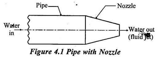
For the transmission of power through pipes, nozzles are fitted on the pipes so that water comes out as jet.
PUMPS
IMPACT OF JET:
1. Introduction
For the transmission of power through pipes, nozzles are fitted on the pipes so that water comes out as jet. If a plate is placed in the path of the jet, a force is exerted by the jet on the plate. The plate may be straight or curved and moving or stationary. The jet strikes the plate in a normal direction or at an angle of inclination. The plates may be fitted on a wheel. The plate can be stationary but hinged at top and so it may rotate under the influence of jet. Nozzle is a device which is used to increase the velocity and corresponding decrease the pressure.
2. Impulse - Momentum Equation:
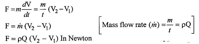
As per Newon's second law of motion, the magnitude of the applied force is equal to the rate of change of momentum. It is given as follows
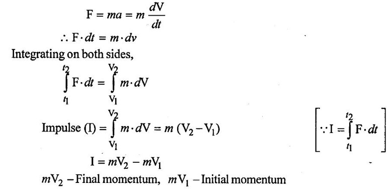
The above equation is called as Impulse - Momentum equation
The above equation represents the force F exerted by the body on the fluid.
As per newton's third law of motion, the force exerted by the fluid on the body will be equal and opposite to force F.
The force exerted by the fluid on the body is,
F = − ρQ (V2 − V1)
F = ρQ (V1 − V2) = m (V1 − V2) In Newton
3. Classification of cases for the jet strike the plate in various position:
(a) Jet striking a stationary flat plate
(i) When plate makes a 90° angle with the jet
(ii) When plate makes an angle other than 90° with the jet.
(iii) When plate is hinged at top and free to rotate and jet may strive at any angle.
(b) Jet strikinga stationary curved plate
(c) Jet striking a moving plate
(i) Plate may be flat
(ii) Plate may be curved
(d) Jet striking a series of flat or curved plates.
1. Jet striking a stationary flat plate:
(i) Let the jet make an angle of 90° with the plate velocity V and cross sectional area of jet as 'a' and its diameter 'd'.
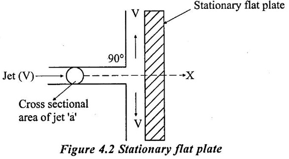
⸫ Force exerted by the jet on the plate
(Fx) = Mass flow rate (m) × Change in velocity (dV) = (ρaV) (V - o)
⸫ Fx = ρ a V2
(ii) Stationary flat plate making angle with horizontal or the jet strikes the plate at ∠θ
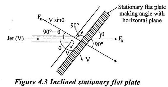
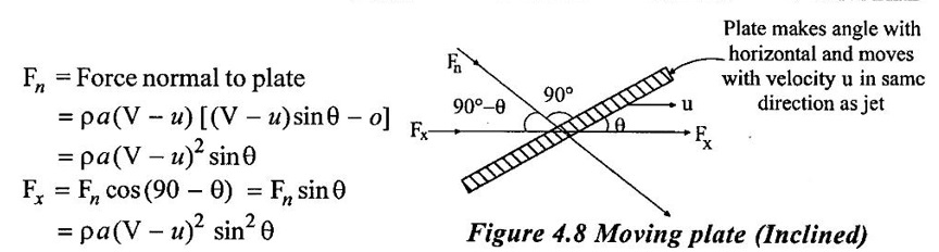
⸫ Component of velocity in direction normal to the plate is V cos (90 - θ) = V sin θ
⸫ Fx = (ρaV) (Vsinθ – o) = ρaV2 sinθ
Now,
Fx = Fn cos (90 - θ) ⇒ Fx = Fn sinθ = ρaV2sin2θ
Fy = ρaV2sin θ cos θ
2. Force Exerted by Jet on Hinged Plate:
Let a plate of dimension (L×B) be suspended from a hinge at O and let its centre of gravity G be at y distance from O. When a horizontal jet strikes the plate with velocity V, the plate gets deflected through angle and its equilibrium in that position is due to the horizontal force Fx of the jet. In its inclined position, G will be at a horizontal distance of (y sin θ) from original position of G of the plate. Taking moment at hinge,
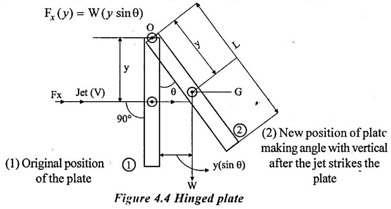
But
Fx = ρaV2
⸫ ρaV2 (y) = W (y sin θ)
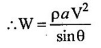
⸫ ρaV2 = W sin θ
Weight (W) = Specific weight × Volume = ρ × g × L × B × t
t = Thickness of plate
ρ = Mass density of plate material
This arrangement is useful in finding out experimental value of CV as V of jet is given by 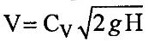 and the head H is known.
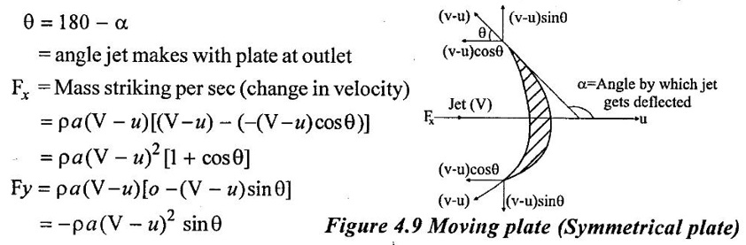
3. Jet striking a stationary symmetrical curved plate at its centre:
Let a jet strike fixed symmetrical and smooth plate centrally, then velocity of water at outlet also same i.e, V. As water mass is divided in to two at the outlet, for calculation of force only one of the outlets is considered.
⸫ Fx = Mass per sec × Change in velocity
= ρaV [V - (-Vcos θ)] = ρaV2 (1 + cos θ)
Fy = ρaV (o - Vsin θ)] = - ρaV2 sin θ
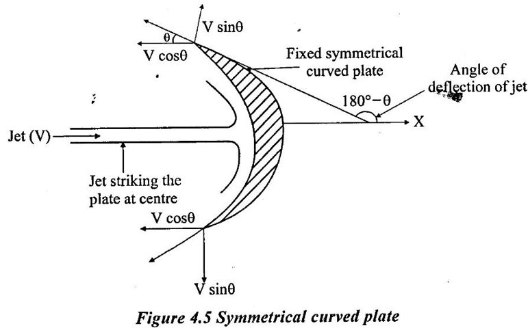
4. Jet striking a stationary curved plate at one end tangentially: (Plate Unsymmetrical)
Let the plate be un symmetrical then θ = angle made by jet at inlet and ϕ = angle made by jet at outlet.
(If plate is symmetrical, θ = ϕ)
Fx = ρaV [Vcos θ - (- Vcos ϕ]
= ρaV2 (cos θ + cos ϕ) for unsymmetrical
= ρaV2 (2 cos θ) for symmetrical
Fy = ρaV2 (sin θ - sin ϕ)
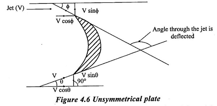
5. Jet striking a moving flat plate:
Case (1) Vertical flat plate:
Let a jet of velocity V strike a plate which is moving at a velocity u in the direction of jet, then mass of water striking the plate is reduced by u.
Fx = Mass striking per sec × Change in velocity
= ρa (V − u) [(V - u) − o] = ρa (V − u)2
Case (2) Inclined flat plate:
6. Jet striking a symmetrical curved plat moving in direction of jet:
7. Jet striking unsymmetrical curved plate moving in direction different from jet:
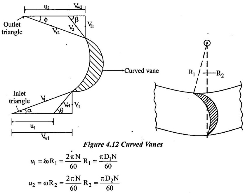
Let the jet strike the plate at one and make ∠α with the horizontal plate is moving with velocity u which is in different direction than that of jet. Relative velocity at inlet (Vr1) will be equal to vector difference of v&u. This gives a velocity triangle at inlet and also at outlet. For both velocity triangles, notations to be followed are as under:
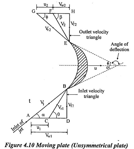
(a) Velocity triangle at inlet:
V1 = Absolute velocity of jet at inlet
u1 = Velocity of plate at inlet
Vr1 = Relative velocity of jet and plate at inlet
α = Angle between V1 & u1
θ = Angle between V r1 & u1 or plate angle at inlet
Vw1 = Velocity of whirl at inlet
Vf1 = Velocity of flow at inlet
(b) Velocity triangle at outlet:
V2 - Absolute velocity of jet leaving the plate
u2 = Velocity of plate at outlet
Vr2 = Relative velocity at outlet
ϕ = Angle between Vr2 & u2 or plate angle at outlet
β = Angle between V2 and u2
Vw2 = Velocity of whirl at outlet
Vf2 = Velocity of flow outlet
θ and ϕ are blade angles at inlet and outlet.
α and β are angles made by jet at inlet and outlet.
Note that u = u1 = u2 and Vr1 = Vr2 if there is no Friction over the plate, assuming plate to be smooth.
Let Fx = Force exerted by jet in direction of motion of the plate.
= Mass of water striking per sec × [Initial velocity - Final velocity of the jet in direction of motion of plate]
Mass/sec = ρaVr1
Initial velocity of jet in direction of motion of the plate
= Vr1 cosθ = Vw1 – u1 from inlet velocity triangle
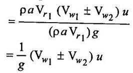
Final velocity of jet in direction of motion of the plate
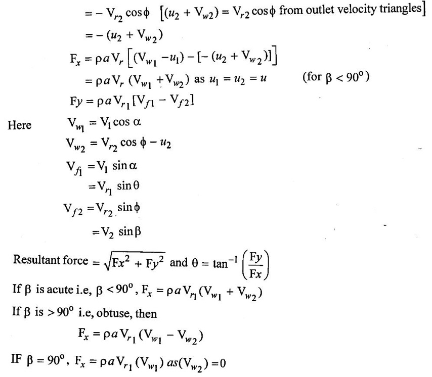
Work done per second per unit weight of striking fluid
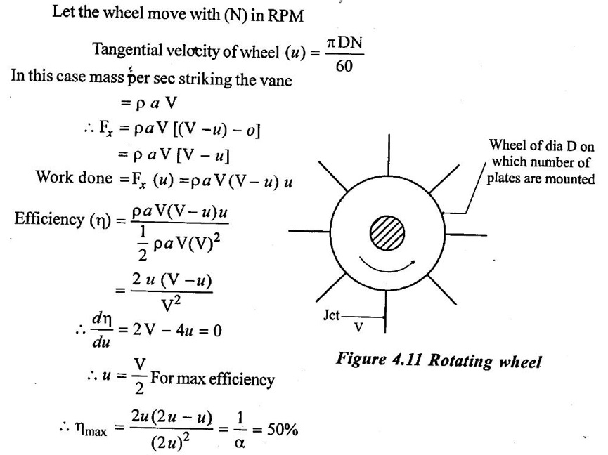
8. Jet striking series of vanes:
Case(i) Flat plates mounted on a wheel:
Let the wheel move with (N) in RPM
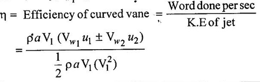
Case (ii) Curved vanes mounted on the wheel:
Moment of water striking the curved vane at inlet
= Mass × tangential component of V1 at inlet
= (ρaV1) (V1 cosα) = ρaV1 (Vw1) (Vw1 = V1 cosα)
Moment of water leaving the vane at outlet
= (ρaV1) (component of V2 in tangential direction)
= ρaV1 (- V2 cosβ)
= - ρaV1 (Vw2) (Vw2 = V2 cosβ)
Angular momentum at inlet
= Momentum at inlet × radius at inlet
= ρaV1 (Vw1)(R1)
Angular momentum at outlet
= - ρaV1 (Vw2) (R2)
⸫ Torque exerted by water on the wheel
T = ρaV1 (Vw1 R1) − (− ρaV1 Vw2 R2)
T = ρaV1 (Vw1 R1) + Vw2 R2) (assuming β as acute)
Work done per sec = Torque × angular velocity
= Τω
= ρaV1 [Vw1 (R1ω) + Vw2 (R2 ω)]
But u1 = ω R1 and u2 = ω R2
⸫ work done per sec = ρaV1 (Vw1 u1 + Vw2 u2)
If β is obtuse,
Work done per sec = ρaV1 (Vw1 u1 + Vw2 u2)
If β = 90°, Vw2 = 0
⸫ work done / sec = ρaV1 (Vw1 u1)