The governing of a turbines is defined as the operation by which the speed of the turbine is kept constant under all conditions of working. It is done automatically by means of a governor, which regulates the rate of flow through the turbines according to the changing load condition on the turbine.
Governing of a turbine is necessary as a turbine is directly coupled to an electric generator, which is required to run at constant speed under all fluctuating load conditions. The frequency of power generation by generator of constant number of pair of poles under all varying conditions should be constant. This is only possible when the speed of the generator, under all changing load condition, is constant. The speed of the generator will be constant, when the speed of the turbine is constant.
When the load on the generator decreases, the speed of the generator increases beyond the normal speed then the speed of the turbine also increase beyond the normal speed. If the turbine or the generator is run at constant speed, the rate of flow of water to the turbine should be decreased till the speed becomes normal. This process by which the speed of the turbine is kept constant under varying condition of load is called governing.
1. Governing of Pelton Turbine (Impulse Turbine)
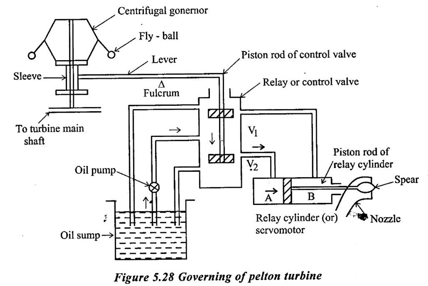
Governing of pelton turbine is done by means of oil pressure governor, which consists of the following party.
(i) Oil sump
(ii) Gear pump also called oil pump, which is driven by the power obtained from turbine shaft.
(iii) The servomotor also called the relay cylinder.
(iv) The control value or the distribution valve (or) relay valve
(v) The centrifugal governor or pendulum which is driven by belt or gear from the turbine shaft.
(vi) Pipes connecting the oil sump with the control valve with servo motor and
(vii) The spear rod or needle.
Fig 5.28 shows the position of the piston in the relay cylinder, position control of relay valve and fly balls of the centrifugal governor, when the turbine is running at the normal speed.
When the load on the generator decreases, the speed of the generator increase. This increases the speed of the turbine beyond the normal speed. The centrifugal governor, which is connected to the turbine main shaft. will be rotating at an increased speed. Due to increase in the speed of the centrifugal governor, the fly-balls move upwards due to increased centrifugal force on them. Due to the upword movement of the fly balls the sleeve will also move upward. A horizontal lever, supported over a flucrum connects the sleeve and the piston rod of the control valve. As the sleve moves up; the lever turn about the fulcrum and the piston rod of the control valve. As the sleve moves up, the lever turn about the fulcrum and piston rod of the ccontrol value move downward. This closes the valve V1 and opens the valve V2 as shown figure 5.28.
The oil pumped from the oil pump to the control valve or reloy valve, under pressure will flow through the valve V2 to the servomotor and will exert force on the face A of the piston of the relay cylinder. The piston along with piston rod and spear will move towards rights. This will decreases the area of flow of water at the outlet of the nozzle. This decrease of area of flow will reduce the rate of flow of water to the turbine which consequently reduces the speed of the turbine. When the speed of the turbine becomes normal the fly balls, sleve, lever and piston rod of control valve come to its normal position as shown in Fig 5.28.
When the load on the generator increases, the speed of the generator and hence of the turbine decrases. The speed of the centrifugal governor also decreases and hence centrifugal force acting on the fly -balls also reduces. This brings the fly-balls in the down ward direction. Due to this, the sleeve moves downward and the lever turns about the fulcrum, moving the piston rod of the control valve in the upward direction. This closes the value V2 and open the value V1. The oil under pressure from the control valve, will move through valve V1 to the servomotor and will exert a force on the face B of the piston. This will move the piston with the piston rod and spear toward Left, increasing the area of flow of water at the outlet of nozzle. This will increase the rate of flow of water to the turbine and consequently the speed of the turbine will also increase till the speed of the turbine becomes normal.
No comments:
Post a Comment