Clarifiers are required where ever the Suspended solids in raw/waste water are higher in concentration. Almost all treatment plant (Clarifiers) sedimentation tanks of circular or sometimes rectangular design.
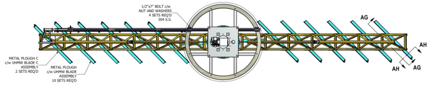
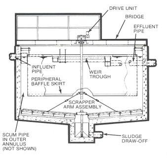
Clarifiers work on the principle of gravity settling. The heavier suspended solids settle in the clarifier due to the quiescent conditions provided in the Clarification zone. The settled solids are swept to the centre well provided for collection of sludge with help of moving scraper blades.
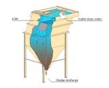
Many a times the natural settling is enhanced by addition of coagulant & polyelectrolyte. The coagulant neutralizes the charges & agglomerates the suspended solids to form micro-floc. The polyelectrolyte brings together these micro-flocs binding them with long chains to make heavy floc which easily settles down. Most of the waste waters contain some scum material which does not settle down & needs to be collected on the surface of the clarifier. Hence a scum removal arrangement is normally provided. A simple clarifier is depicted in sketch below.
Configurations:
The clarifiers are designed based on the intended function & the space availability. In conventional waste water treatment plants there are normally two types:
a. Primary Clarifier
b. Secondary Clarifier
Specific applications require the following:
a. Lamella Clarifier
b. Solids Contact clarifier
There are many design variation among the above type but available space & flow dictates whether it will be a circular or rectangular clarifier.
Circular Clarifier:
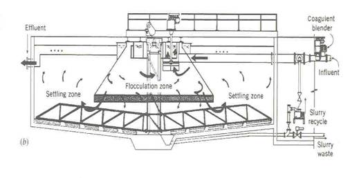
The Clarifier design can be applied to water or wastewater treatment systems. It includes a larger influent well to provide the required flocculation time. Mixing is also added to achieve economical flocculation.
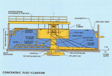
Mechanical flocculation is proved by either concentric ‘stacked’ drives or independent mixers. Tanks start at ten feet in diameter and larger. Circular sludge collectors are available in either full or half bridge designs.
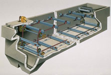
Rectangular Clarifier:
The Chain & Scraper Sludge Collection System provides maximum sludge concentrations and scum/floating solid removal regardless of the size or application.
Rectangular clarification, a separation process commonly used in very large or space constrained municipal and industrial spaces, removes both settled and suspended solids from liquids.
To assist the gravity settling many innovations are made in clarifier design.
A very popular design has Inclined plates (Lamella Clarifier) in the clarifying zone for rapid settling of flocs. The plates are placed at an angle (of 55-65º) & the water travels upwards. The solids (flocs) due to inherent weight cannot travel with same velocity & tend to settle on the plates provided. The slope of the plates ensures that the solids slide down to the collection chamber.
Another design involves creating slow turbulence in the settled sludge itself. The upward moving sludge helps to bring down the settleable flocs faster to sludge zone.
Clarifiers find application in almost all water & waste water plants depends on the influent SS and turbidity. The major applications would be as below.
a. Raw Water Clarification
b. Primary Effluent Clarification
c. Secondary Effluent Clarification
d. Sludge Thickener
e. Lime Soda Softening