In the previous chapter, we have studied about the direct tensile and compressive stress as well as simple shear stress and strain.
ANALYSIS OF STRESSES
1. INTRODUCTION
In the previous chapter, we have studied about the direct tensile and compressive stress as well as simple shear stress and strain. In many situations, machine components are subjected to two or more stresses on a given plane. In such situation, the resultant stress across any cross section will be neither normal or tangential to the plane. We shall analyse the nature and intensity of stresses on planes, other than that, which is at right angles to the line of action of the force.
2. PRINCIPAL PLANES AND PRINCIPAL STRESSES
The planes which have no shear stress are known as principal planes. These planes carry only normal stresses. The magnitude of normal stresses, acting on a principal plane, are known as principal stresses.
3. METHODS FOR DETERMINING STRESSES ON OBLIQUE PLANE
The stresses on oblique plane are determined by the following methods:
1. Analytical method
2. Graphical method
4. ANALYTICAL METHOD
In analytical method, the following cases will be considered for determining stresses on oblique plane.
1. A member subjected to a direct stress in one plane.
2. A member subjected to direct stresses in two mutually perpendicular directions.
3. A member subjected to a simple shear stress.
4. A member subjected to a direct stress in one plane accompanied by a simple shear.
5. A member subjected to two direct stresses in mutually perpendicular directions accompanied by a simple shear stress.
5.A MEMBER SUBJECTED TO A DIRECT STRESS IN ONE PLANE
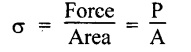
Consider a member of uniform cross sectional area A and unit thickness subjected to a principal tensile stress σ as shown in Fig. 1.39.
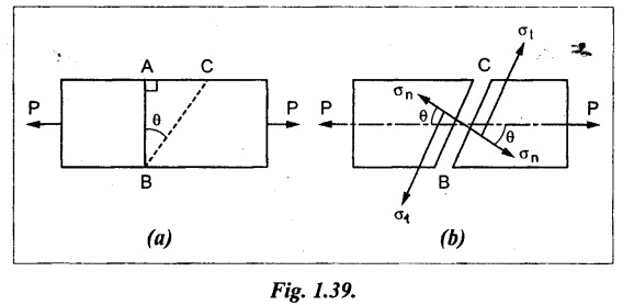
The stress on a section perpendicular to the line of action (i.e., AB) is given by
The stress on section AB is only normal stress, no shear is acting.
Now consider a section BC which is at an angle 0 with the normal cross section AB.
The magnitude of this tensile stress on BC is less than that of AB, since the resisting section has a bigger area. The stress, on the section BC, is parallel to the axis of the member. This stress is not normal to the section BC. The normal and tangential stresses on section BC are calculated as follows.
The tensile force perpendicular to the plane BC,
Pn = P cos θ
The tensile force parallel to the plane BC,
Pt = P sin θ
Normal stress across the section BC,
Tangential stress across the section BC,
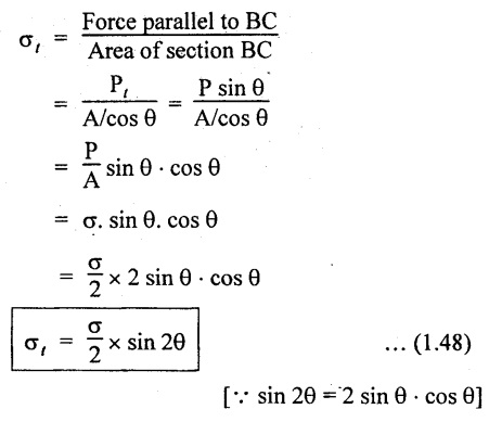
From the equation σn, we see that the normal stress σn is maximum when cos2θ is maximum, and cos2 θ will be maximum when θ = 0° as cos2 0 = 1. But when the θ = 0 the section BC coincide with section AB. Therefore the normal cross section AB will carry the maximum direct stress.
⸫ Maximum normal stress = σ cos2 θ = σ cos2 0° = σ
From the equation σt, it is observed that the tangential stress σt is maximum when sin 2 θ is maximum. And sin 2 θ will be maximum when 2 θ = 1 or 2 θ = 90° or 270°.
⸫ θ = 45° or 135°
Therefore the shear stress will be maximum on two planes inclined at 45° and 135° to the normal section AB.
It is thus obvious, that the maximum tangential stress is half of the normal stress.
6. A MEMBER SUBJECTED TO DIRECT STRESSES IN TWO MUTUALLY PERPENDICULAR DIRECTIONS
Consider a rectangular body PQRS of uniform cross-sectional area, A and unit thickness subjected to mutually perpendicular direct tensile stresses as shown in Fig. 1.40.
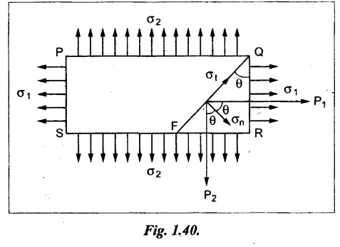
Let FQ is the oblique section on which we are required to find out the stresses.
Let,
σ1 - Major tensile stress on face PS and QR
σ2 - Minor tensile stress on face PQ and SR
P1 - Tensile force on section RQ
Tangential forces P1 and P2 are also acting on the oblique section FQ. The force P1 is acting in the axial direction and the force P2 is acting perpendicular to it. Therefore two forces can be resolved into two components i.e., one is normal to the plane FQ and the other is tangential to the plane FQ.
Let Pn = Total force normal to the plane FQ
Normal stress across the plane FQ,
Similarly, tangential stress (i.e., shear stress) along the plane FQ.
The resultant stress on section FQ is
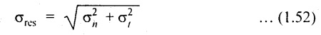
Obliquity (ϕ)
The angle made by the resultant stress with normal of the reference oblique plane is called as obliquity (ϕ). It is shown in Fig.1.41.
In mathematical form.
Principal Planes
We know that the plane which has no shear is called principal plane. To find out the principal plane the shear stress equation should be equated to zero.
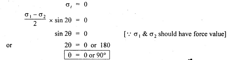
Thus we see that there are two principal planes at right angles to each other.
When θ = 0°,
Thus the maximum normal stress will occur when the θ = 0°.
When θ = 90°,
Thus the minimum normal stress will occur when the θ = 90°.
Therefore one of the principal plane carries maximum direct stress whereas the other is minimum.
Maximum Shear Stress
The shear stress across the plane FQ is maximum when,
Thus, the shear stress will be maximum on two planes inclined at 45° and 135° to the normal section.
Maximum shear stress,
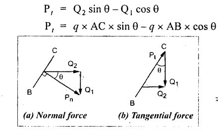
7. A MEMBER SUBJECTED TO A SIMPLE SHEAR STRESS
Consider a section PQRS of uniform cross sectional area A and of unit thickness and is subjected to a simple shear stress (q) as shown in Fig.1.42.
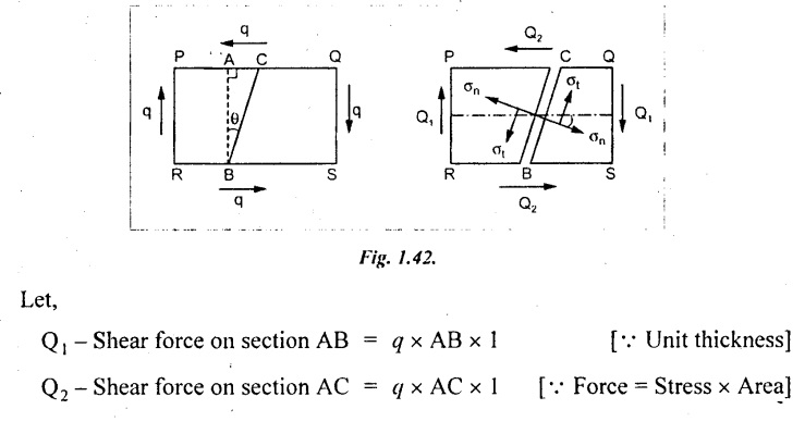
Shear stress Q1 and Q2 are acting on the oblique section BC. The force Q1 is acting in the axial direction and is resolved into two components Q1 cos θ and Q1 sin θ in tangential and normal direction respectively.
Similarly, the force Q2 which is acting on the perpendicular direction to Q1 is also resolved into two components Q2 sin θ and Q2 cos θ in tangential and normal directions respectively.
Normal force acting on section BC,
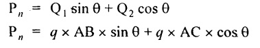
Tangential force acting on section BC,
Normal stress on section BC,
Similarly,
Tangential stress on section BC,
Maximum shear stress, and principal planes are obtained similar manner as previous case.
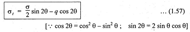
8. A MEMBER SUBJECTED TO A DIRECT STRESS IN ONE PLANE ACCOMPANIED BY A SIMPLE SHEAR STRESS
Consider a rectangular body PQRS of uniform cross sectional area A and unit thickness subjected to a tensile stress in one plane accompanied by a simple shear stress as shown in Fig.1.43.
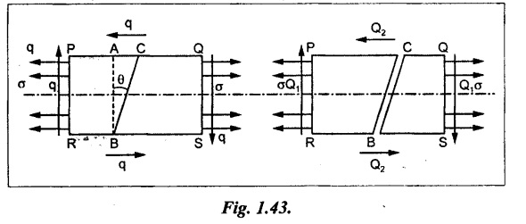
Let,
P - Tensile force on section AB = σ × AB × 1
Q1 - Shear force on section AB = q × AB × 1
Q2 - Shear force on section AC = q × AC × 1
Normal force acting on section BC,
Tangential force acting on section BC,
Normal stress on section BC,
Normal stress,
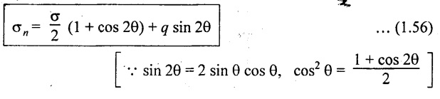
Tangential stress on section BC,
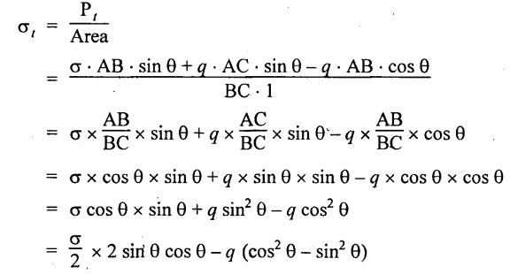
Tangential or shear stress,
Position of Principal Planes
We know that the plane on which shear stress is zero are known as principal planes. The position of principal planes are obtained by equating the tangential stress to zero. (ie., σt = 0).
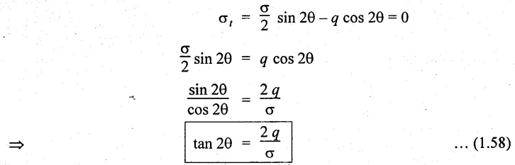
But the tangent of any angle in a right angle triangle is the ratio of height of right triangle to the base of right angle triangle.
i.e.,
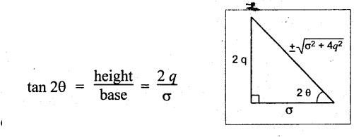
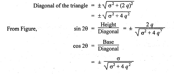
From the diagram, the diagonal of the triangle may be written by
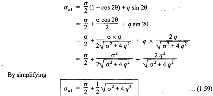
Maximum and minimum intensity of principal stresses
Take + ve sign as case (i)
Substituting cos 2θ & sin 2θ values in the equation σn
If, we consider -ve sign as case (ii),
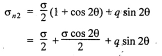
Substituting cos 2θ and sin 2θ values,
Note:
(i) When σn1 maximum, the value of σn2 will be minimum and vice versa.
(ii) If σn1 is tensile in nature, σn2 will be compressive and vice versa.
Maximum Shear Stress
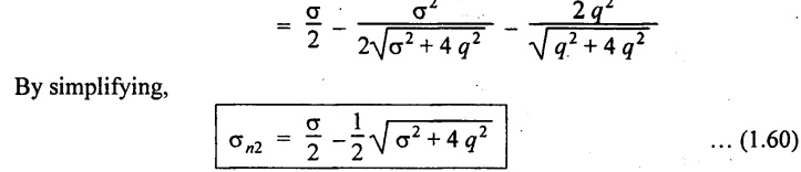
The shear stress will be maximum or minimum when
Substituting the above sin 2θ & cos 2θ equations in tangential stress equation σt.
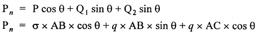
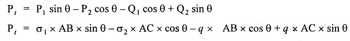
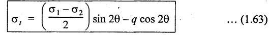
9. A MEMBER SUBJECTED TO TWO DIRECT TENSILE STRESSES IN MUTUALLY PERPENDICULAR DIRECTION ACCOMPANIED BY A SIMPLE SHEAR STRESS
Consider a rectangular body PQRS of uniform cross sectional area A and of unit thickness. This member is subjected to the two direct tensile stresses in mutually perpendicular direction and a simple shear stress as shown in Fig.1.44.
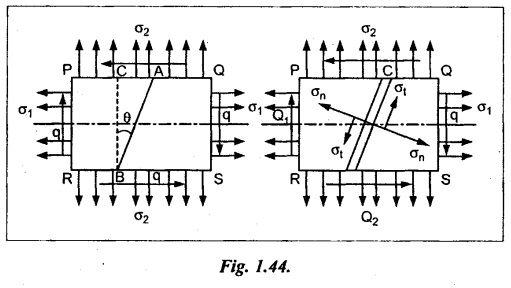
Let,
P1 - Tensile force on section AB due tensile stress σ1.
σ1 × AB × 1 = σ1 × AB
P2 - Tensile force on section AC due tensile stress σ1.
σ2 × AC × 1 = σ2 × AC
Q1 - Shear force on section AB
= q × AB × 1 = q × AB
Q2 - Shear force on section AC
= q × AC × 1 = q × AC
Resolving the above forces normal to BC,
Total normal force on section BC,
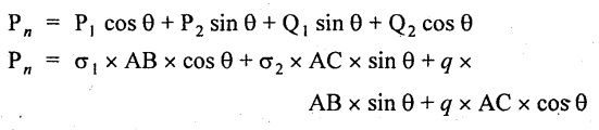
Resolving the forces along the plane BC,
Total tangential force,
Normal stress across the section BC,
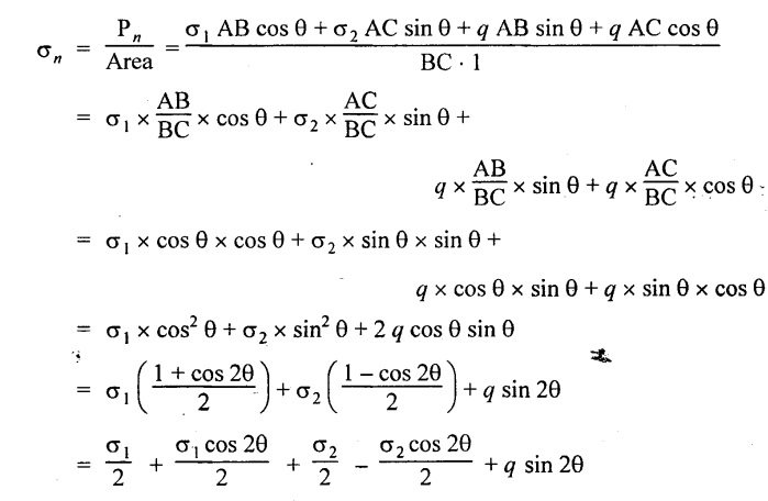
Normal stress,
Tangential or shear stress across the section BC,
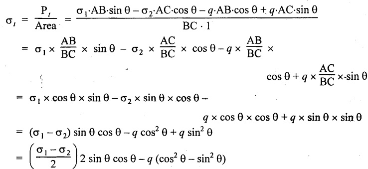
Tangential or shear stress
Position of Principal planes
It can be derived in similar way like that of previous case.
(i) Position of principal plane can be found out by using
(ii) Major principal stress
(iii) Minor principal stress
Maximum shear stress
This is also derived similar to that of previous case.
Maximum shear stress
10. GRAPHICAL METHOD
In the previous topics we have seen that the method of getting normal and tangential stress intensities across any oblique plane inclined 0° to the major principal stress σ. These can also be obtained very easily by a graphical construction as follows.
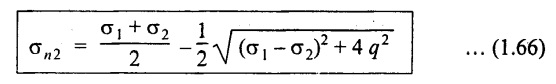
Case (i): A body subjected to two mutually perpendicular unequal like stresses.
Like stresses means both the stresses are either tensile or compressive in nature.
Unlike stresses means one stress in tensile whereas other is compressive in nature.
Consider a rectangular member of uniform cross sectional area A subjected to two unequal like stresses which is tensile in nature.
Let,
σ1 - Major principal tensile stress
σ2 - Minor principal tensile stress
θ - Angle made by the oblique section with the minor principal axis.
Construct the circle of stresses as given below.
1. Draw two perpendicular lines meeting at O representing the direction of stresses σ1 and σ2.
2. With O as centre, draw the concentric circles of radii OA and OB equal to the stresses σ1 and σ2 to some scale.
3. Draw the line XY through O which makes an angle θ with the plane of σ2.
4. From O, draw the line OCD which is normal (i.e., perpendicular) to the line XY and meeting the circles at C and D.
5. Draw DE perpendicular to OA and CF perpendicular to DE.
6. Join OF which is the resultant stress σ across the plane XY..
7. From F, draw a line FG perpendicular to OD.
8. OG represents normal stress and FG represents tangential stress on the oblique plane.
Note: For all kind of stresses it may be + ve or- ve, the construction is similar to the above steps only the position of the point F will change.
The position of point F will be as follows.
1. If σ1 and σ2 are +ve, the point will lie in first quadrant.
2. If σ1 is –ve and σ2 is +ve the point will lie in second quadrant.
3. If σ1 and σ2 both are -ve, the point will lie in 3rd quadrant.
4. If σ1 is +ve and σ2 is -ve, the point will lie on 4th quadrant.
Note: + represents tensile stress and -ve represents compressive stresses.
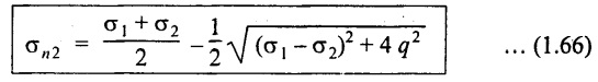
Case (ii): A body subjected to two equal mutually perpendicular and unlike principal stresses
Consider a rectangular body subjected to two equal mutually perpendicular and unlike stresses acting as shown in Fig.1.46.
Construct the circle of stresses given below.
1. Draw two perpendicular lines meeting at O representing the direction of stresses σ1 and σ2.
2. With O as centre, draw a circle of radius OA or OB equal to the stresses σ1 or σ2 since the two stresses are equal magnitude.
3. Draw the line XY through O which makes an angle with plane of σ2.
4. Draw the line OC which is normal to the line XY and meeting the circle at C.
5. If we follow the same procedure as in the previous case we can get the points D, F and G at a point C. (i.e., C, D, F and G are coincide)
6. We already know that if σ1 is +ve and σ2 is -ve, the resultant stress will lie 4th quadrant. Therefore, get the mirror image of F in 4th quadrant as shown in Fig. Note this point as F'.
7. Now, OF' represent the intensity of stress on the oblique plane. It is numerically equal to OF but inclined at an angle 2θ to the normal.
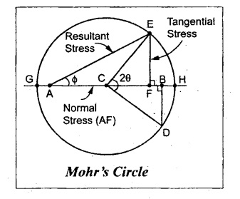
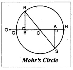
11. MOHR'S CIRCLE METHOD
The another method which is frequently used to find out the normal, tangential and resultant stresses in oblique plane is Mohr's circle method. It is also a graphical method.
Case (i): A body subjected to two mutually perpendicular unequal and like principal stresses
Consider a rectangular body subjected to two unequal and like principal stresses σ1 and σ2 which are perpendicular to each other as shown in Fig.1.47.
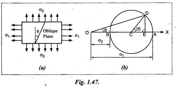
Let,
σ1 - Major principal stress
σ2 - Minor principal stress and
θ - Angle between the minor principal stress and the oblique section.
Construct the Mohr's circle as given below.
1. Draw the horizontal line OX and set off OA and OB to scale to represent σ1 and σ2 respectively.
2. Bisect BA at C. With C as centre draw a circle which radius is equal to BC or AC. This circle is known as Mohr's circle.
3. Through C, draw a line CD making an angle 20 with CA.
4. From D, draw DE perpendicular to AB.
5. Join OD which represents the resultant stress σ on an oblique plane.
6. The angle DOA is called the angle of obliquity which is denoted by ϕ.
7. OE and DE represent normal and tangential stress on oblique plane respectively.
Note:
1. The normal stress in maximum when the point D is at A and minimum when D is at B. It is obvious from the above, that the tangential stress is zero when the normal stress is maximum or minimum.
2. The tangential stress is maximum when the line E is at C and minimum when E is at A or B, since the tangential stress is perpendicular to AB.
3. The angle of obliquity (ϕ) is maximum when the line OD is tangent to the Mohr's circle.
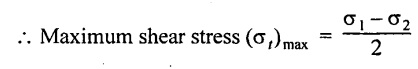
Case (ii): A body subjected to two mutually perpendicular unequal and unlike principal stresses.
Consider a rectangular body subjected to two unequal and unlike principal stresses σ1 and σ2 which are perpendicular to each other as shown in Fig.1.48.
Let,
σ1 - Major principal tensile stress
σ2 - Minor principal tensile stress
θ - Angle between the minor principal stress and the oblique plane.
Construct the Mohr's circle as given below.
1. Draw the horizontal line and set off OA and OB opposite to each other to represent σ1 and σ2 respectively, since the stresses are unlike (i.e., one is tensile whereas other is compressive)
2. Bisect BA at C. With C as centre draw a circle which radius is equal to BC or AC. This circle is known as Mohr's circle.
3. Through C, draw a line CD making an angle 2θ with CA.
4. From D, draw DE perpendicular to OA.
5. Join OD which represents the resultant stress σ on an oblique plane.
6. The angle DOA is called the angle of obliquity (ϕ).
7. OH and OG represent normal and tangential stresses on oblique plane respectively.
8. The maximum shear stress is equal to the radius of the Mohr's circle.

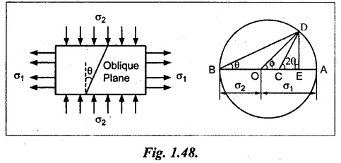
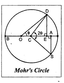
Case (iii): A body subjected to two mutually perpendicular unequal like stresses accompanied by a simple shear stress.
Consider a rectangular body subjected to two mutually perpendicular unequal like tensile stresses σ1 and σ2 accompanied by a simple shear stress q as shown in Fig. 1.49.
Let,
σ1 - Major principal tensile stress
σ2 - Minor principal tensile stress
q - Simple shear stress and
θ - Angle between the minor principal stress and the oblique plane.
We are now going to find out the normal, tangential and resultant stress on the oblique section.
Construct the Mohr's circle as given below:
1. Draw the horizontal line and set off OA and OB equal to σ1 and σ2 on the same side to some suitable scale, since both the stresses are tensile.
2. Bisect BA at C.
3. From A, draw perpendicular line AS which is equal to shear stress q to the same scale.
4. With C as centre and CS as radius draw a circle which meets the line OX at G and H. This circle is known as Mohr's circle.
5. Draw a line CD which makes an angle 20 with CS.
6. Joint the point D with O and also draw a line DE which is perpendicular to OA.
7. OE and DE represents normal and tangential stresses on the oblique section respectively. OD represents the resultant stress.
8. OH and OG will give the maximum and minimum value of normal stress to scale and CS will give the maximum value of shear stress.
12. SOLVED PROBLEMS ON ANALYSES OF STRESS
Example 1.63:
The mild steel block has cross section of 50 mm × 50 mm carries an axial load of 35 kN which is compressive in nature. Find the normal and tangential stresses across a plane through the point at 30° to the axis of the block. Also find the maximum shear stress in the block.
Given:
Area of cross section, A = 50 mm × 50 mm = 2500 mm2
Load, P = 35 kN.
= 35,000 N
θ = 30°
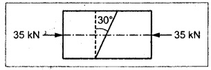
To find:
σn and σt, (σ)max
Solution:
Result:
Normal stress, σn = 10.5 N/mm2
Tangential stress, σt = 6.062 N/mm2
Maximum shear stress, (σ)max = 7 N/mm2
Example 1.64:
A member subjected to a pull P consists of two pieces of wooden frame of cross section 35 mm × 15 mm connected by glued joints as shown in Fig.
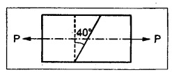
Calculate the maximum permissible value of P which can withstand, if the permissible normal and tangential stress in glue are 13 N/mm2 and 8 N/mm2.
Given:
Axial pull - P
Area of cross section, A = 35 mm × 15 mm
= 525 mm2
Normal stress, σn = 13 N/mm2
Tangential stress, σt = 8 N/mm2
Θ = 40°
To find:
Maximum permissible value of P
Solution:
We know that,
Normal stress, σn = σ cos2 θ
σ = 22.153 N/mm2
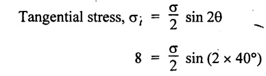
σ = 16.24 N/mm2
The safe stress is minimum of the above two values.
Therefore, the safe stress, σ = 16.24 N/mm2
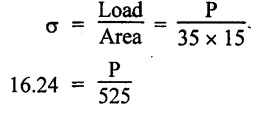
Permissible value, P = 8526 N or 8.526 kN
Result:
Maximum permissible value of load, P = 8.526 kN
Example 1.65:
A 5 mm thick aluminium plate has a width of 300 mm and a length of 600 mm subjected to pull of 15000 N and 9000 N respectively in axial and transverse direction. Determine the normal, tangential and resultant stresses on a plane 40° to the greatest stress.
Given:
Width, b = 300 mm
Length, l = 600 mm
Thickness, t = 5 mm
Axial load, P1 = 15000 N
Transverse load, P2 = 9000 N
To find:
Normal (σn), tangential (σt) and resultant stresses on a plane 40° to the greatest stress.
Solution:
Analytical method:
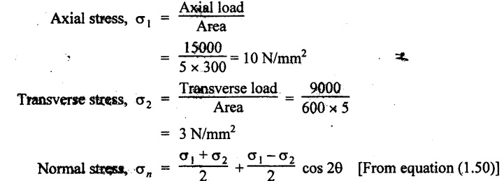
In this problem maximum stress is σ which is horizontal.
Therefore, θ = 90° - 40° = 50° to the vertical
Graphical method:
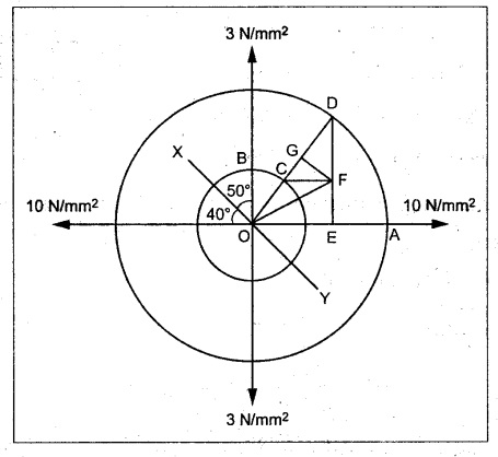
1. Draw two perpendicular lines meeting at O representing the direction of stresses 10 N/mm2 and 3 N/mm2.
2. With O as centre, draw two concentric circles of radii OA and OB equal to 10 N/mm2 and 3 N/mm2 to some scale.
3. Draw the line XY through O which makes an angle 50° with the plane of 3 N/mm2 stress.
4. From O, draw the line OCD which is perpendicular to the line XY and meeting the circle at C and D.
5. Draw DE perpendicular to OA and draw CF perpendicular to DE.
6. Join OF which is equal to resultant stress σres across the plane XY.
7. From F, draw a line FG perpendicular to OD.
By measurements,
Normal stress, σn = OG = 6 N/mm2
Tangential stress, σt = GF 3.4 N/mm2
Resultant stress, σres = OF = 6.9 N/mm2
Result:
Normal stress, σn = 6 N/mm2
Tangential stress, σt = 3.4 N/mm2
Resultant stress, σres = 6.9 N/mm2
Example 1.66:
The principal stresses at a point in the section of a heat exchanger shell are 18 MPa (tensile) and 10 MPa (compressive) acting mutually perpendicular to each other. Determine the normal, shear and resultant stress intensities on a plane whose normal is inclined at 60° to 10 MPa stress. Find also the maximum shear stress.
Given:
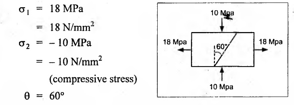
To find:
Normal (σn), shear (σt), resultant stress (σres) and maximum shear stress, (σt)max
Solution:
Analytical method:
Maximum shear stress,
Mohr's Circle Method:
1. Draw a horizontal line and set off OA and OB opposite to each other to represent 18 N/mm2 and 10 N/mm2 respectively to some scale, since the stresses are unlike.
2. Bisect BA at C. With C as centre draw a circle of radius equal to BC or CA. The circle is known as Mohr's circle.
3. Through C, draw a line CD making an angle 120° with CA.
4. From D, draw DE perpendicular to OA.
5. Join OD which represents the resultant stress.
By measurements,
Normal stress, σn = OE = -3 N/mm2
Tangential stress, σt = DE = 12 N/mm2
Resultant stress, σres = OD = 12.4 N/mm2
Maximum shear stress, (σt)max = Radius of Mohr's circle
= BC or AC 14 N/mm2
Result:
Normal stress, σn = - 3 N/mm2
Shear stress, σt = 12.12 N/mm2
Resultant stress, σres = 12.485 N/mm2
Maximum shear stress, (σt)max = 14 N/mm2
Example 1.67:
At a point in a strained material, the principal stresses are 100 N/mm2 and 70 N/mm2 both tensile. Graphically or otherwise locate the planes for which the resultant intensity of stress is inclined at 10 degrees to the normal. State the magnitudes of this intensity. Also locate the plane for which the resultant intensity has maximum inclination with its normal.
Given:
σ1 = 100 N/mm2
σ1 = 70 N/mm2
ϕ = 10°
To find:
1. Inclination of oblique plane (θ) when ϕ = 10°
2. Resultant stress when ϕ = 10°
3. θ when ϕ is maximum
Solution:
Mohr's Circle method:
1. Draw a horizontal line and set off OA and OB to some scale to represent 100 N/mm2 and 70 N/mm2 respectively.
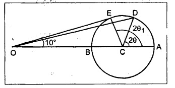
2. Bisect BA at C. With C as centre draw a circle of radius BC or CA. This circle is the Mohr's circle.
3. Through O, draw a line OD making an angle ϕ = 10° with OA.
4. Join CD which makes an angle 2θ with BA.
By measurement,
2θ = 81°
⸫ θ = 40° 30' or 130° 30'
Intensity of resultant stress, σres = CD = 14.5 N/mm2
Through O, draw a line which is tangent to the Mohr's circle (E). This represents the resultant intensity of maximum inclination.
2θ1 = 95°
⸫ θ1 = 47° 30' or 137° 30'
Results:
Inclination of oblique plane when ϕ = 10° is 40° 30' or 130° 30'
Intensity of resultant stress when ϕ = 10° is 14.5 N/mm2
Inclination of oblique plane when ϕ is maximum is 47° 30' or 137° 30'.
Example 1.68:
At a point in a strained material the intensity of tensile stress is 60 N/mm2 and a shear stress of 25 N/mm2. Graphically or otherwise locate the planes for which the shear stress is zero. What will be the normal stress on such a lane?
Given:
σ = 60 N/mm2
q = 25 N/mm2
To find:
1. Oblique plane for which shear stress is zero.
2. Normal stress.
Solution:
The shear stress on the oblique plane is given by,
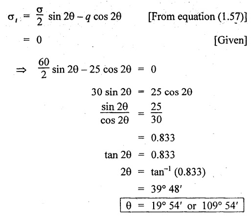
Normal stress on that plane
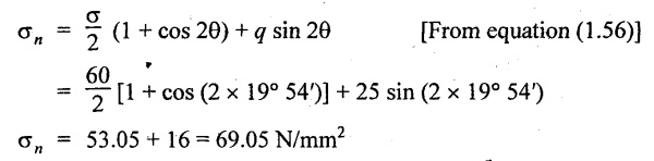
Result:
There are two plane at angles 19° 54′ and 109° 54′ on which the shear stress is zero.
Normal stress on that plane is 69.05 N/mm2.
Example 1.69 :
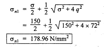
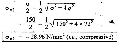
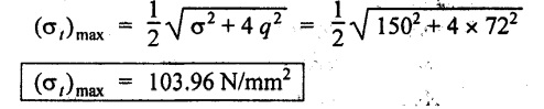
A rectangular block is subjected to a compressive stress of 150 N/mm2 on one plane and accompanied by a shear stress of 72 N/mm2. Determine the position of principal planes and maximum and minimum intensity of direct stress. Find also the maximum intensity of shear stress.
Given:
σ = 150 N/mm2
q = 72 N/mm2
To find:
Position of principal plane (θ)
Maximum and minimum value of direct stress
(σn1 & σn2).
Maximum shear stress
Solution:
Analytical method:
For this case we know that,
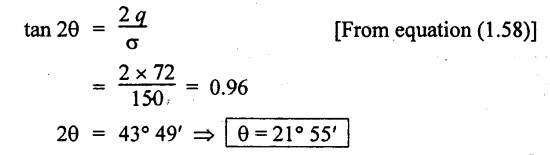
Maximum value of direct (normal) stress,
Minimum value of direct stress,
Maximum shear stress,
Mohr's Circle method:
1. Draw a horizontal line and set off AB equal to 150 N/mm2 to some suitable scale.
2. Bisect AB at C.
3. From B draw a perpendicular line BD equal to shear stress 72 N/mm2.
4. With C as a centre and CD as a radius draw a circle. This circle is known as Mohr's circle.
5. The circle meets the horizontal line at G and H.
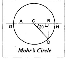
By measurements,
Result:
Position of principal plane, θ = 21° 55'
Maximum direct stress, σnl = 178.96 N/mm2
Minimum direct stress, σn2 = - 28.5 N/mm2
Maximum shear stress, (σt)max = 103.96 N/mm2
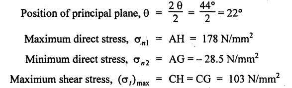
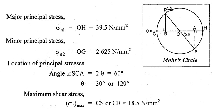
Example 1.70:
A bar of steel is under a tensile stress of 65 N/mm2 at the same time, it is accompanied by a shear stress of 22.5 N/mm2. Find the normal, shear and resultant stresses across a plane at an angle of 45° with the axis of major tensile stress. Also find the maximum intensity of shear stress.
Given:
σ = 65 N/mm2
q = 22.5 N/mm2
θ = 45°
To find:
σn, σt, σres and (σt)max
Solution:
Analytical method:
Mohr's Circle method:
1. Draw horizontal line set off AB equal to tensile stress 65 N/mm2 to some scale.
2. Bisect AB at C.
3. Through B, draw line BD which is equal to shear stress 22.5 N/mm2 and perpendicular to AB.
4. With C as center and CD as radius draw a circle which is known as Mohr's circle.
5. Draw a line CE which makes an angle 20 (i.e., 90°) with CD and intersecting Mohr's circle.
6. Join AE which is equal to the resultant stress.
By measurement,
Normal stress, σn = AF = 55 N/mm2
Tangential stress, σt = EF= 32.5 N/mm2
Resultant stress, σres AE = 63.88 N/mm2
Maximum shear, (σt)max = CH = CG = 39.5 N/mm2
Result:
Normal stress, σn = 55 N/mm2
Tangential stress σt = 32.5 N/mm2
Resultant stress, σres = 63.88 N/mm2
Maximum shear, (σt)max = 39.5 N/mm2
Example 1.71:
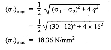
At a point in a strained body subjected to two mutually perpendicular normal tensile stresses of magnitude 30 MPa and 12 MPa accompanied by a shear stress of 16 MPa. Locate the principal planes and evaluate the principal stresses. Also calculate the maximum intensity of shear stress and specify its planes.
Given:
σ1 = 30 MPa = 30 N/mm2
σ2 = 12 MPa = 12 N/mm2
q = 16 MPa
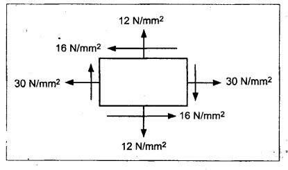
To find:
1. Location of principal planes, θ
2. Principal stresses, σn1, σn2
3. Maximum shear stress, σt max
Solution:
Analytical method:
For this case, by using relation,
Major principal stress,
Minor principal stress,
Maximum shear stress,
Mohr's Circle Method:
1. Draw a horizontal line and set off OA and OB equal to the stressés 30 N/mm2 and 12 N/mm2 on the same side to some suitable scale, since both are tensile stresses.
2. Bisect BA at C.
3. From A and B draw perpendicular lines AS and RB which is equal to shear stress 16 N/mm2 to the same scale as shown in Fig.
4. With C as center and CS or CR as radius draw a circle which meets the horizontal line at G and H.
By measurement,
Results:
1. Location of principal planes, θ = 30° 19' or 120° 19'
2. Major principal stress, σn1 = 39.36 N/mm2
3. Minor principal stress, σn2 = 2.642 N/mm2
4. Maximum shear stress, (σt) max = 18.36 N/mm2
Example 1.72:
At a certain point of a control lever of an aeroplane, there are normal stresses of 75 MN/m2 tension and 45 MN/m2 compression on two planes at right angles to one another together with shearing stresses of 65 MN/m2 on the same plane when it just takes off. After it gathers full speed, it is observed that the loading on this element gets so increased, that the stresses reach value x times those observed at the start. Compute the maximum value x if the maximum direct stress in the materials not to exceed 115 MN/m2 and the maximum shearing stress is not to exceed 120 MN/m2. Hence or otherwise, state values of the principal stresses and the maximum shearing stresses actually developed and locate their planes.
Given:
When the planes take off,
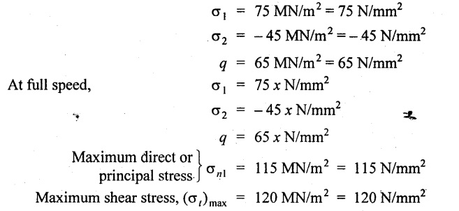
To find:
1. Value of 'x'.
2. Actual principal stresses and their planes.
Solution:
We know that, for this case
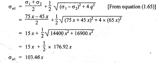
Since the maximum principal stress is limited to 115 N/mm2
103.46 x = 115
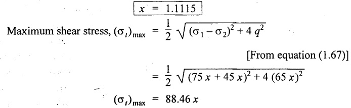
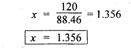
Since the maximum shear stress is limited to 120 N/mm2
88.46 x = 120 N/mm2
We should take the minimum of above two values of x. That can be the maximum permissible value.
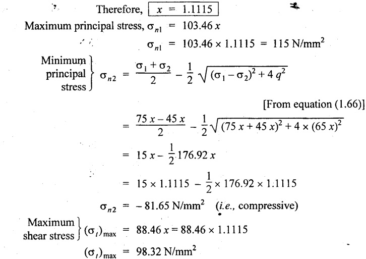
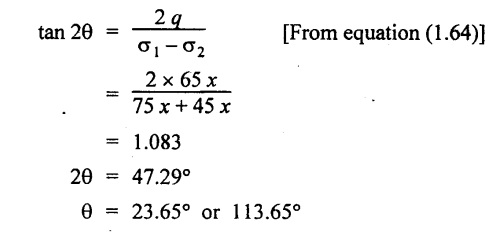
Location of principal stresses,
Result:
1. Value of x = 1.1115
2. Maximum principal stress, σnl = 115 N/mm2
3. Minimum principal stress, σn2 = - 81.65 N/mm2
4. Maximum shear stress, (σt) max = 98.32 N/mm2
5. Position of principle planes, θ = 23.65° or 113.65°
Example 1.73:
At a point in a beam there are tensile stresses of 50 N/mm2 and 30 N/mm2 respectively at right angles to one another, together with a shearing stress. If the major principal stress is 66 N/mm2 tensile, evaluate the shear stress on the two planes. Calculate the minor principal stress and also the maximum shear stress.
Given:
σ1 = 50 N/mm2
σ1 = 30 N/mm2
σ1 = 66 N/mm2
To find:
1. Shear stress, q
2. Minor principal stress, σn2
3. Maximum shear stress, (σt)max
Solution:
Analytical method:
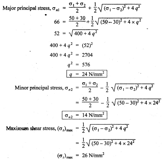
Mohr's Circle method:
1. Draw a horizontal line and set off OA and QB equal to the stresses 50 N/mm2 and 30 N/mm2 on the same side to some suitable scale.
2. Bisect BA at C.
3. In the problem, it is given that the major principal stress is 66 N/mm2. Therefore set off OH as 66 N/mm2 to the same circle.
4. With C as a center and CH as a radius draw a circle which is called as Mohr's circle.
5. Draw perpendicular lines from A and B to meet the circle at S and R respectively.
6. Now the distance AS or BR is shear stress which we are looking for.
7. OG is the minor principal stress and CH or CG is the maximum shear stress.
By measurement,
Shear stress, q = = AS or BR 24 N/mm2
Minor principal stress, σn2 = OG = 14 N/mm2
Maximum shear stress, (σt)max = CG or CH
= 26 N/mm2
Result:
1. Shear stress, q = 24 N/mm2
2. Minor principal stress, σn2 = 14 N/mm2
3. Maximum shear stress, (σt)max = 26 N/mm2
Example 1.74:
The state of stress at a given point in a material component is σx = 400 MPa, σy = -300 MPa, τxy = 200 MPa
Working from Mohr's circle method, determine, for a plane inclined at 40° to the plane on which the latter stress acts.
(a) The magnitude and angle of obliquity of the resultant stress, (b) The normal and tangential component stresses, (c) maximum value of shear stress.
Given:
σ1 = 400 MPa = 400 N/mm2
σ2 = -300 MPa = - 300 N/mm2
q = 200 MPa = 200 N/mm2
θ = 40°
To find:
1. Resultant stress, σres
2. Angle of obliquity, ϕ
3. Normal and tangential stress, σn & σt
4. Maximum shear stress, (σt)max
Solution:
1. Draw a horizontal line and set off OA and OB equal to the stresses 400 N/mm2 and 300 N/mm2 on opposite sides to some suitable scale, since both the stresses are opposite. (i.e., one is tensile and the other is compressive).
2. Bisect BA at C.
3. From A draw a perpendicular line AS which is equal to shear stress of 200 N/mm2 to the same scale.
4. With C as centre and CS as radius draw a circle. This is known as Mohr's circle.
5. Draw a line CD which makes an angle 2θ (i.e., 80°) with CS.
6. Join the point D with O and also draw a line DE which is perpendicular to OA.
By measurement,
Resultant stress, σres = OD = 440 N/mm2
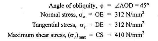
Results: