university solved problems on cantilever beam: Transverse Loading on Beams and Stresses in Beam - Strength of Materials
UNIVERSITY SOLVED PROBLEMS ON CANTILEVER BEAM
Example 2.11:
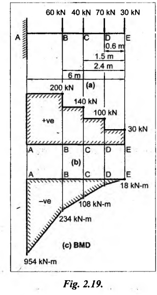
A cantilever 6m long carries load of 30, 70, 40 and 60 kN at distance of 0, 0.6, 1.5 and 2.4m respectively from the free end. Draw the SF and BM diagrams for the cantilever.
Given:
As shown in Fig.2.19(a).
To draw:
SFD and BMD
Solution:
SF calculation:
SF at E = 30 kN
SF at D = 30 + 70 = 100 kN
SF at C = 100 + 40 = 140 KN
SF at B = 140 + 60 = 200 kN
SF at A = 200 KN
Join all the values by straight horizontal line as shown in Fig.2.19(b).
BM calculation:
BM at E = 0
BM at D = - 30 × 0.6 = - 18 kN-m
BM at C = -30 × 1.5 - 70 × 0.9
= - 108 kN-m
BM at B = - 30 × 2.4 - 70 × 1.8 - 40 × 0.9
= - 234 kN-m
BM at A = -30 × 6 - 70 × 5.4 -40 × 4.5 - 60 × 3.6
= -954 kN-m
Join all the values by straight inclined lines as shown in Fig. 2.19(c).
Result:
The SFD and BMD are as shown in Fig.2.19(b) & (c) respectively.
13. SFD AND BMD FOR SIMPLY SUPPORTED BEAMS
Case (a): SSB with central point load
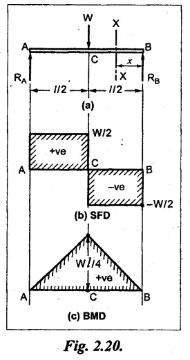
Consider a beam AB of span 'l' simply supported at ends and carrying a concentrated load W at the center C as shown in Fig.2.20(a).
In SSB, the supports that provide 'upward force' to balance the vertical downward load is called reactions. But it do not prevent rotation of the beam. Total reaction at supports (i.e., RA + RB) is equal to the algebraic sum of the loads on the beam.
The reaction at the supports A and B are denoted by RA and RB.
To calculate the values of RA and RB, taking moments about the support A or B.
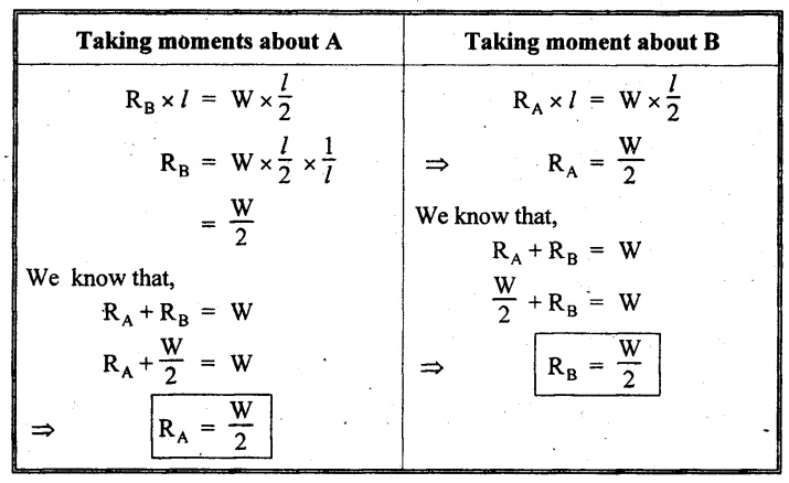 SFD
SFD
Consider, any section X-X at a distance of x from B.
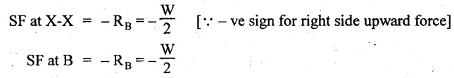
SF remains constant between B and C and is equal to -W/2.
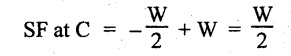
SF remains constant between C and A and is equal to W/2.

Join the obtained values by a straight line as shown in Fig.2.20(b), since, the load is point load.
BMD
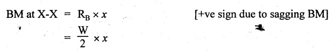
The above equation is a first degree equation, it represents a straight line variation.
When x = 0,
BM at B = 0.
When x = l/2,
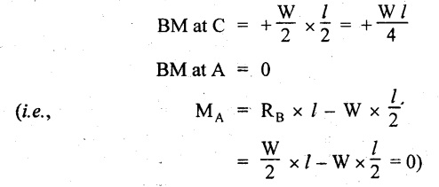
Generally in SSB, the BM values are zero at both supports. Draw the BMD as shown in Fig.2.20(c):
Case (b): SSB with UDL
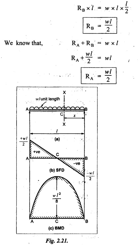
Consider a SSB carrying UDL of w/unit length as shown in Fig.2:21(a).
To find the reactions RA and RB, take moments about A.
SFD
Consider a section X-X at a distance of x from the end B.
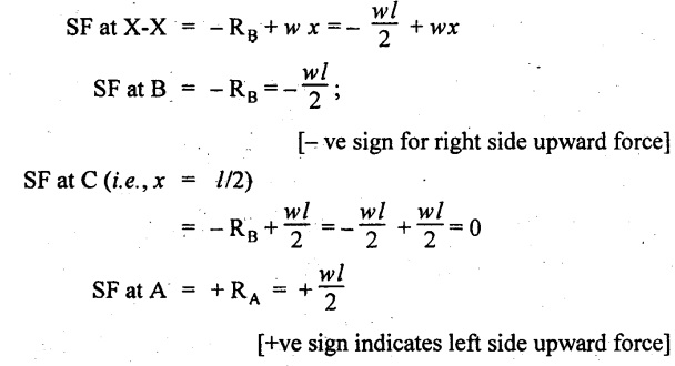
SF is equal to –wl/2 at B and increases gradually by a straight line law, to zero at the mid point of the beam, beyond which it continues to increase uniformly to a value of wl/2 at point A as shown in Fig.2.21(b).
BMD
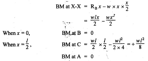
From above results note that BM is zero at the supports and increases parabolically towards its center and attains maximum value (wl2 /8) at the center. When the BM is maximum, the SF changes its sign. The BMD is shown in Fig.2.21(c).
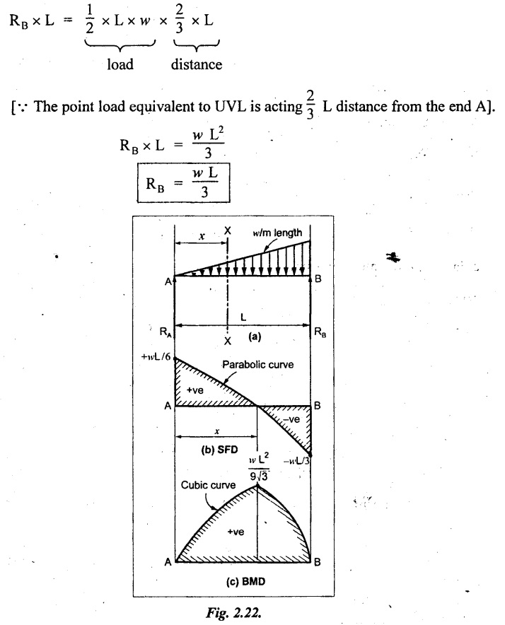
Case (c): SSB with Uniformly Varying Load
Consider a SSB of length L carrying uniformly varying load zero at one end and w per m length at the other end as shown in Fig.2.22(a).
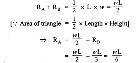
Reactions
Taking moment about A,
We know that,
Consider the section X-X at a distance of 'x' m from A.
SF calculation:
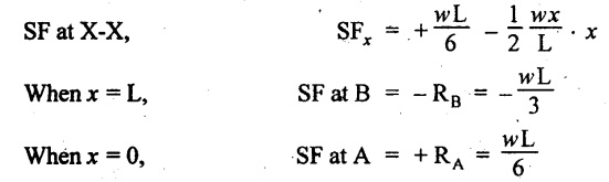
Join the above values by parabolic curve as shown in Fig.2.22(b).
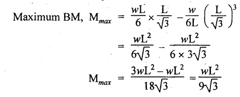
BM calculation:
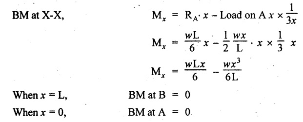
The maximum BM will occur where the SF changes its sign which is at a distance of x m from the end B. Therefore equate the SF equation to zero.
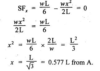
The BM is maximum at a distance of 0.577L from end A.
We know that,
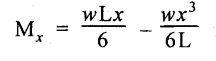
Substitute x value in the above equation,
Join the BM values by cubic curve, since the general equation is cubic equation as shown in Fig.2.22(c).
14. SOLVED PROBLEMS ON SSB
Example 2.12 :
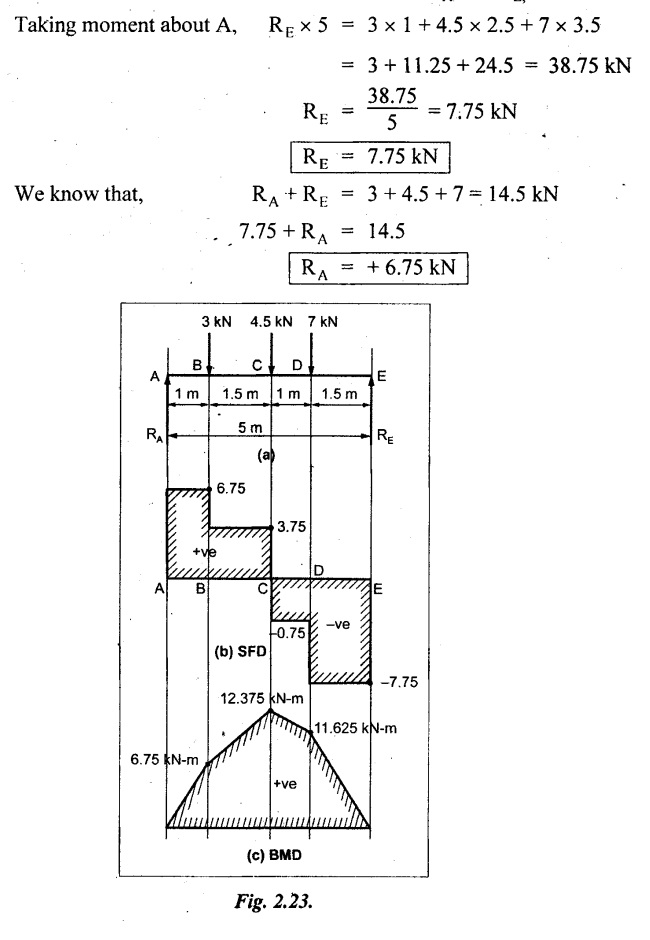
A beam freely supported over an effective span of 5 m carries point loads 3 kN, 4.5 kN and 7 kN at 1, 2.5 and 3.5 m respectively from the left hand support. Construct the SF and BM diagrams.
Given:
As shown in Fig.2.23(a).
To draw:
SFD and BMD.
Solution:
To find the reactions at supports RA and RE,
SF calculation:
SF at E = -RE = -7.75 kN
[-ve sign indicates right side upward force]
SF at D = - RE + 7 kN
= -7.75 + 7 = -0.75 kN
SF at C = -RË + 7 kN +4.5 kN = −7.75 + 7 + 4.5 = 3.75 kN
SF at C may be calculated by adding SF at D and load at C.
i.e., SF at C = − 0.75 kN + 4.5 = 3.75 kN
SF at B = -RE + 7 kN + 4.5 kN + 3 kN
= − 7.75 + 7 + 4.5 + 3 = 6.75 kN
or
SF at B = 3.75 + 3 = 6.75 kN
SF at A = 6.75 kN = RA (+ve sign indicates left side upward force)
Draw the SFD as shown in Fig.2.23(b).
BM calculation:
Taking moment about respective cross section to the right side.
BM at E = 0
BM at D = + RE × 1.5 m = 7.75 × 1.5 = 11.625 kN-m
BM at C = +RE × 2.5 m −7 × 1 = 7.75 × 2.5 – 7
= 12.375 kN-m
BM at B = +RE × 4 - 7 × 2.5 – 4.5 × 1.5.
= 7.75 × 4 - 17.5 - 6.75 = + 6.75 kN-m
BM at A = 0
Maximum BM will occur where the SF is zero or sign changes. In this problem the maximum BM is 12.375 kN-m where the SF is zero. Join the values as shown in Fig.2.23(c).
Result:
The SFD and BMD are as shown in Fig.2.23(b) & (c) respectively.
Example 2.13:
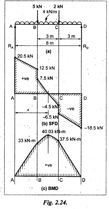
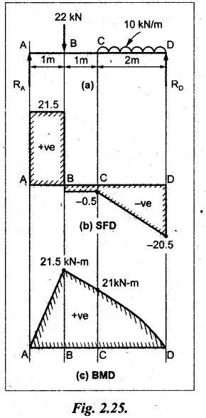
A beam of 8 m span simply supported at its end carries loads of 2 kN and 5 kN at a distance of 3 m and 6 m respectively from right support. In addition, the beam carries a UDL of 4 kN/m for its entire length. Draw the SF and BM diagrams.
Given:
As shown in Fig.2.24(a).
To draw:
SFD and BMD
Solution:
Taking moment about A,
RD × 8 m = 2 kN × 5 m + 5 kN × 2 m + 4 kN/m × 8m × 8/2
= 10 + 10 + 128 = 148
RD = 148/8 = 18.5 kN
RA + RD = 2 kN + 5 kN + 4 kN/m × 8 m
RA + RD = 39 kN
18.5 + RA = 39
SF calculation:
SF at D = -RD = – 18.5 kN
SF at C (without point load 2 kN)
= - RD + 4 kN/m × 3 m
= -18.5 + 12 = -6.5 kN
SF at C (with point load)
= -RD + 4 kN/m × 3 m + 2 kN
= - 4.5 kN
SF at B (without point load 5 kN)
= - RD + 4 kN/m × 6m + 2 kN
= - 18.5 + 24 + 2 = 7.5 kN
SF at B (with point load)
= 7.5 kN + 5 kN = 12.5 kN
SF at A = +RA = 20.5 kN
[⸪ SF at A should be equal to reaction at A i.e., RA]
Join the SF values as shown in Fig.2.24(b).
BM calculation:
BM at D = 0
Maximum BM:
The maximum BM will occur where the SF changes its sign. Let x be the distance from A where the SF changes its sign as shown in Fig.2.24(b). SF equation at that point can be written and equating it to zero,
RA - 5 kN - 4 kN/m × x m = 0
20.5 – 5 - 4x = 0
x = 3.875 m
The BM will be maximum at 3.875m from A or 4.125m from D.
Taking moment about the point where the SF is zero,

= 40.03 KN-m
Result:
SFD and BMD are shown in Fig.2.24 (b) and (c) respectively.
Example 2.14 :
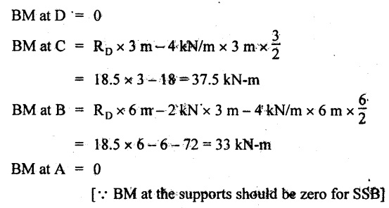
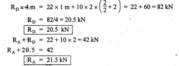
A freely supported beam of 4m effective span carries a load of 10 kN/m over the right hand half of the span and a point load 22 kN at a distance of 1 m from the left support. Construct the SF and BM diagrams.
Given:
As shown in Fig.2.25(a).
To draw:
SFD and BMD
Solution:
Taking moment about A,
SF calculation:
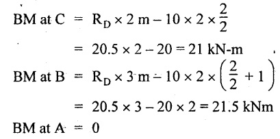
SF at D = -RD = -20.5 KN
SF at C = - RD + 10 × 2
= -20.5 + 20 = -0.5 kN
SF at B = -0.5 + 22 kN = 21.5 kN
SF at A = 21.5 = RA
Join the SF values between C and D by inclined line since the load is UDL.
Refer Fig.2.25(b).
BM calculation:
BM at D = 0
Join the BM values between C and D by parabolic curve and other by a straight inclined line.
The maximum BM is placed at B, because the SF is changes its sign.
Result:
SFD and BMD are shown by Fig.2.25(b) and (c) respectively.
Example 2.15:
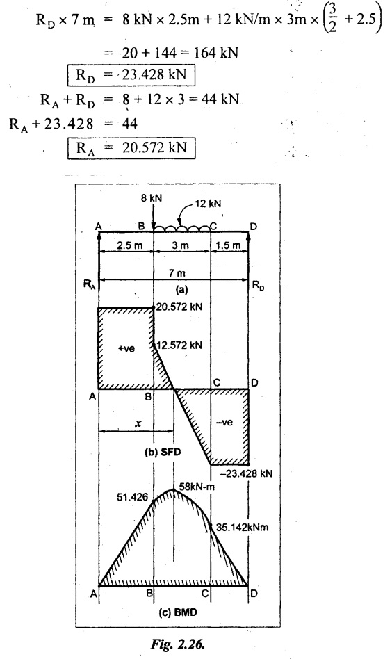
A simply supported beam of 7 m span has a load of 12 kN/m uniformly distributed over 3 m. It is 1.5 m away from the right. In addition it has a point load of 8 kN at 2.5 m from the left hand support.
Given:
As shown in Fig.2.26(a).
To draw:
SFD and BMD
Solution:
Taking moment about A,
SF calculation:
SF at D = -RD = - 23.428 kN
SF at C = -23.428 kN [⸪ No load between C and D]
SF at B (without point load)
= -RD + 12 kN/m × 3 m
= - 23.428 + 36 = 12.572 kN
SF at B (with point load)
= 12.572 kN + 8 kN = 20.572 kN
SF at A = + RA = 20.572 kN
Draw the SFD as shown in Fig.2.26(b).
BM calculation:
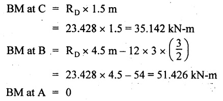
BM at D= 0
The maximum BM is situated at a distance of x from the point A where the SF changes its sign. SF equation at that point is,
RA - 8 kN - 12 × (x −2.5) m = 0
[ ⸪ the UDL is acting only (x -2.5) m length]
20.572 – 8 - 12x + 30 = 0
x = 3.547 m
The maximum BM is acting at 3.547m from end A or 3.453m from end D.
Maximum BM:
Taking moment about the point where the SF is zero,
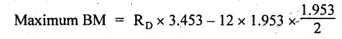
[⸪ The UDL is acting for a distance of (3.453-1.5) m from the right side]
= 23.428 × 3.453 - 22.885
Maximum BM = 58 KN-m
Join the BM values between B and C by a parabolic curve. Since the load is UDL. Other values are connected by straight line. Refer Fig.2.26(c).
Result:
SFD and BMD are shown in Fig.2.26(b) and (c) respectively.
Example 2.16:
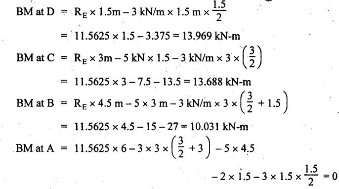
A beam is freely supported over a span of 6m. It carries a UDL of 3 kN/m over 1.5 m from the left hand support and also from the center upto the right hand support. It has, besides, two point loads of 2 and 5 kN at 1.5 and 4.5 m from left hand support. Construct the SF and BM diagrams.
Given:
As shown in Fig.2.27(a).
To draw:
SFD and BMD.
Solution:
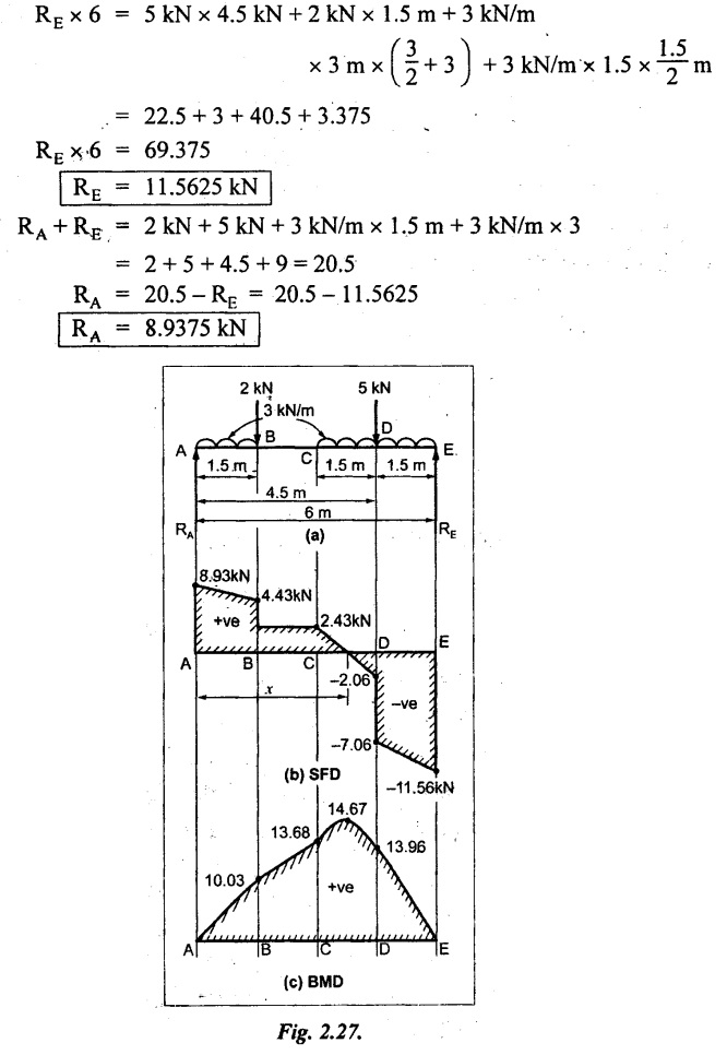
Taking moment about A,
 SF calculation:
SF at E = - RE = - 11.5625 kN
SF at D (without point load)
= - RE + 3 kN/m × 1.5 m
= -11.5625 + 4.5 = - 7.0625 kN
SF at D (with point load)
= -7.0625 kN + 5 kN = 2.0625 kN
SF at C = RE + 5 kN + 3 kN/m × 3 m
= -11.5625 + 5 + 9 = 2.4375 kN
Similarly, SF at B = 2.4375 kN + 2 kN = 4.4375 kN
SF at A = 4.4375 kN + 3 kN/m × 1.5 m = 8.9375 kN
or
SF at A = + RA = 8.9375 kN
Draw the SF diagram as shown in Fig.2.27(b).
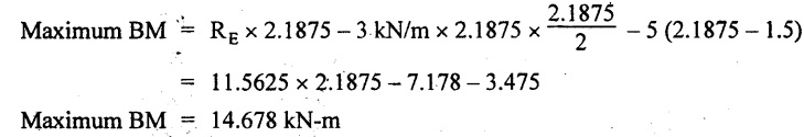
BM calculation:
BM at E = 0
Maximum BM:
We know that, the BM will be maximum where the SF changes its sign. SF equation for a distance x from end A.
8.9375 kN - 3 kN/m × 1.5 - 2 kN − 3 kN/m × (x − 3m) = 0
8.9375 - 4.5 – 2 - 3x + 9 = 0
x = 3.8125 m
The BM will be maximum at 3.8125 m from end A or 2.1875 m from E.
Taking moment about the point where SF is zero,
Join the BM values between C & E and A & B by a parabolic curve because UDL is acting there. Join the BM value by straight line between B & C as shown in Fig.2.27(c).
Result:
SFD and BMD are shown by Fig.2.27(b) and (c) respectively.
Example 2.17:
A simply supported beam of length 5m carries a uniformly varying load of 800 N/m run at one end to zero at the other end. Draw the SF and BM diagrams for the beam. Also calculate the position and magnitude of maximum bending moment.
Given:
As shown in Fig.2.28(a).
To draw:
SFD and BMD. Find maximum BM and its position.
Solution:
Taking moment about A,
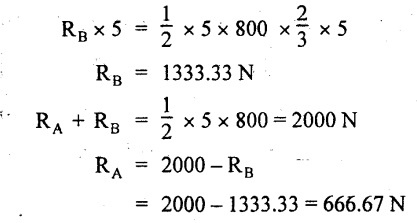
SF calculation
SF at B = -RB = -1333.33 N
SF at A = RA = 666.67 N
Join the above values by parabolic curve as shown in Fig.2.28(b).
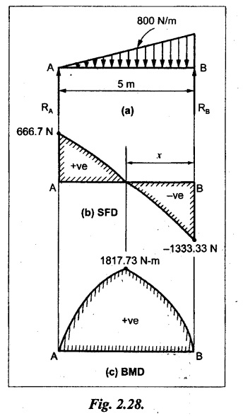
BM calculation:
BM at A = 0
BM at B = 0
Maximum BM calculation:
The BM is maximum where. the SF changes its sign. The SF is zero or changes its sign at a distance of x m from end B. The SF equation at that point is,
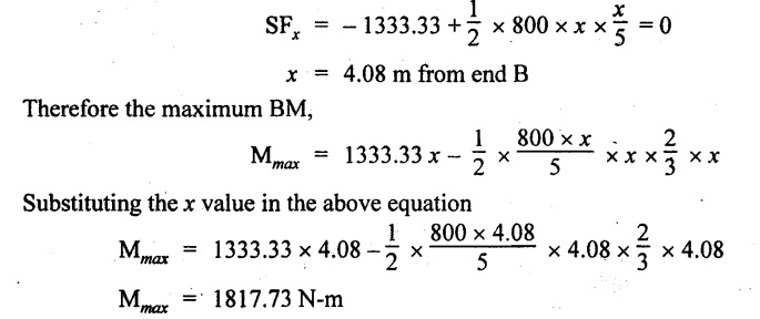
Result:
(i) The maximum BM is at a distance of 4.08m from end B and its value 1817.73 N-m.
(ii) The SFD and BMD are shown by Fig.2.28(b) and (c) respectively.
Example 2.18:
Draw the shear force and bending moment diagram for the beam as shown in Fig.2.29 (a).
Given:
As shown in Fig.2.29(a).
To draw:
SFD and BMD.
Solution:
For this type of problem, the load is divided into two types.
1. One is UDL of 300N acting entire length.
2. Other is UVL of (950 – 300) N acting at end A and zero at end B.
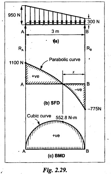
Now it is very simple to calculate the SF and BM.
Taking moment about A,
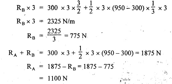
SF calculation:
SF at B = - RB = - 775 N
SF at A = RA = 1100 N
Join the above values by parabolic curve as shown in Fig.2.29(b).
BM calculation:
BM at B = 0
BM at A = 0
Maximum BM calculation:
Let the SF is zero at a distance of x m from B.
The SF equation at that point is,
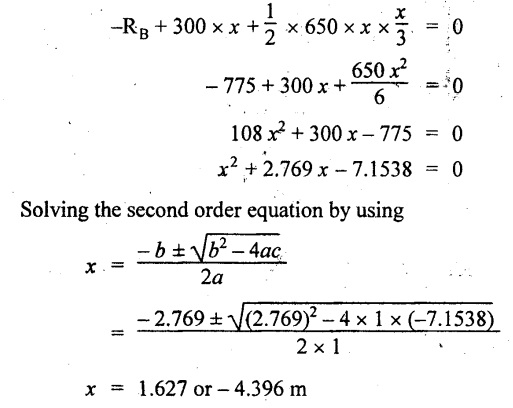
Negative value is not possible. Therefore, x = 1.627 m from B.
The maximum BM is,

Join all the values by cubic curve as shown in Fig.2.28(c).
Result:
The SF and BM diagrams are shown in Fig.2.29(b) and (c) respectively.
Example 2.19 :
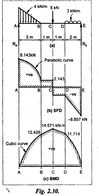
Analyse the beam as shown in Fig. 2.30(a) and draw the SFD and BMD.
Given:
As shown in Fig.2.30(a).
To draw:
(i) Maximum BM,
(ii) Draw SFD and BMD
Solution:
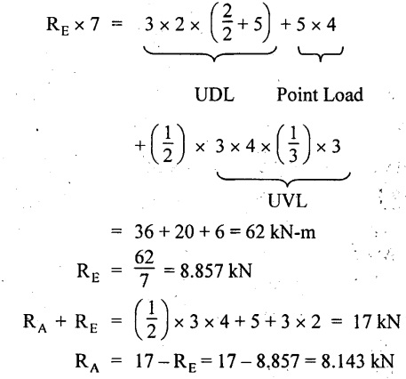
Taking moment about A,
SF calculation:
SF at E = -RE = - 8.857 kN
SF at D = - 8.857 + 3 × 2 = 2.857 kN
SF at C = - 2.857 +5 = +2.143 kN
SF at B = 2.143 KN
SF at A = RA = 8.143 KN
Join all the values by corresponding curves as shown in Fig.2.30(b).
BM calculation:
BM at E = 0
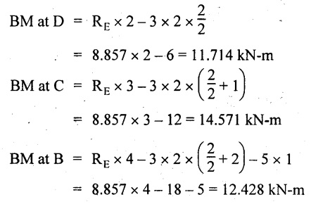
BM at A = 0
Join the BM values by respective curves as shown in Fig.2.30(c).
Result:
(i) The maximum BM value is 14.571 KN-m.
(ii) The SFD and BMD are as shown in Fig.2.30(b) and (c) respectively.
university solved problems on ssb: Transverse Loading on Beams and Stresses in Beam - Strength of Materials
UNIVERSITY SOLVED PROBLEMS ON SSB
Example 2.20:
A beam 8m long is simply supported at the ends and carries a uniformly distributed load of 1500 N/m and three concentrated load of 1000 N, 2000 N and 4000 N acting respectively at the left quarter point, center point and right quarter point. Draw SFD and BMD.
Given:
As shown in Fig.2.31(a).
To draw:
SFD and BMD
Solution:
Taking moment about A,
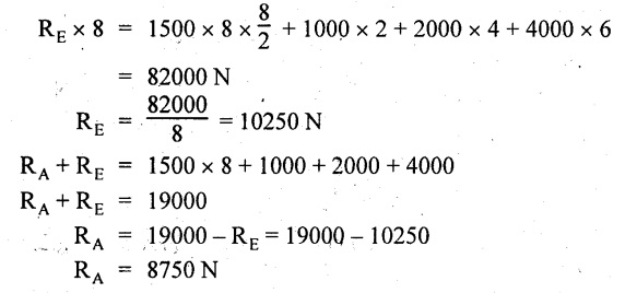
SF calculation:
SF at E = -RE = -10,250 N
SF at D (without point load)
= -RE + 1500 × 2
= -10,250 + 1500 × 2 = − 7250 N
SF at D (with point load)
= -7250 + 4000 = - 3250 N
SF at C (without point load)
= -3250 + 1500 × 2 = - 250 N
SF at C (with point load)
= -250 + 2000 = 1750 N
SF at B (without point load)
= 1750 + 1500 × 2 = 4750 N
SF at B (with point load)
= 4750 + 1000 = 5750 N
SF at A = RA = 8750 N
Join all the values by straight inclined lines as shown in Fig.2.31(b).
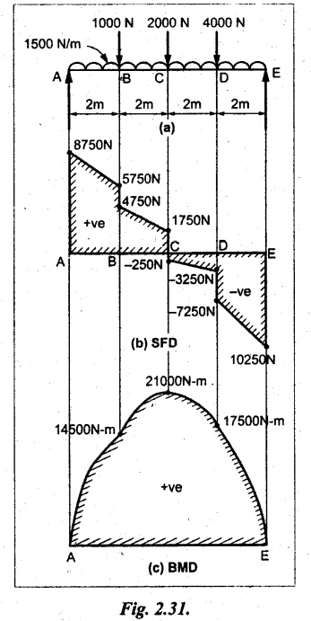
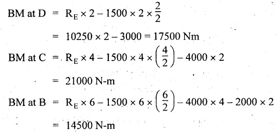
BM calculation:
BM at E = 0
BM at A = 0
Join all the values by parabolic curves as shown in Fig.2.31(c).
Result:
The SFD and BMD are as shown in Fig.2.31(b) & (c) respectively.
Example 2.21 :
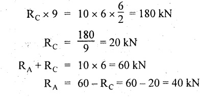
Draw the shear force and bending moment diagrams for a simply supported beam of span 9m. The beam carries a UDL of 10 kN/m for a distance of 6m from the left support. Find the maximum value and their position. Give the values at important points in the diagram.
Given:
As shown in Fig.2.32(a).
To draw:
SFD and BMD
Solution:
Taking moment about A,
SF calculation:
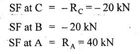
Join all the values between A and B by straight inclined lines as shown in Fig.2.32(b).
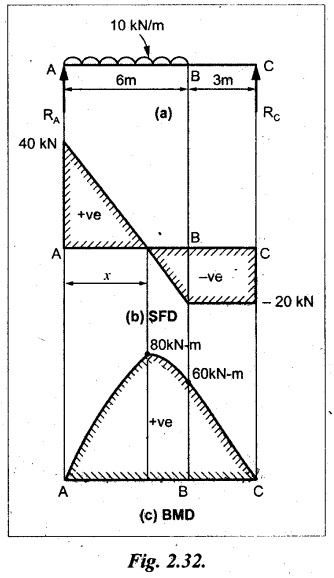
BM calculation:
BM at C = 0
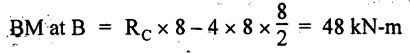
BM at B = RC × 3 = 20 × 3 = 60 kN-m
BM at A = 0
Join all the values between A & B by parabolic curves as shown in Fig.2.32(c).
BM will be maximum when SF is zero. The SF is zero at a point x distance from A.
The SF equation when it is zero,
SFX = RA – 10 × x = 0
40 - 10x = 0
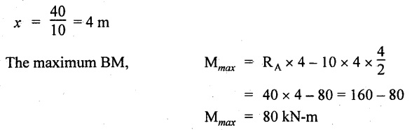
Result:
The SFD and BMD are as shown in Fig.2.32(b) & (c) respectively.
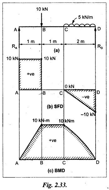
Example 2.22:
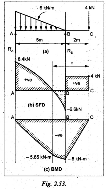
Draw the shear force and bending moment diagram for the beam shown in Fig.2.33(a). Find the maximum values and their positions.
Given:
As shown in Fig.2.33(a).
To draw:
SFD and BMD
Solution:
Taking moment about A,
SF calculation:
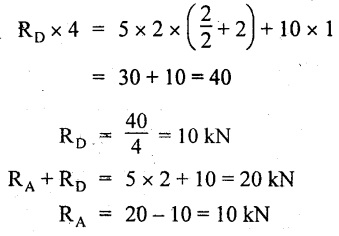
SF at D = - RD = -10 kN
SF at C = -10 + 5 × 2 = 0 kN
SF at B = 0 + 10 = 10 kN
SF at A = RA = 10 kN
Join the values between C and D by straight inclined line and all other values by horizontal line.
BM calculation:
BM at D = 0
BM at A = 0
Join the values between C and D by parabolic curve and all other values by inclined straight lines.
Result:
The SFD and BMD are as shown in Fig.2.33(b) & (c) respectively.
Example 2.23:
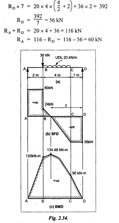
Analyse the simply supported beam shown in Fig.2.34(a) and sketch the SF and BM diagram.
Given:
As shown in Fig.2.34(a).
To draw:
SFD and BMD
Solution:
Taking moment about A,
SF calculation:
SF at D = -RD = -56 kN
SF at C = -56 kN
SF at B (without point load) = -56 + 20 × 4 = 24 kN
SF at B (with point load) = 24 + 36 = 60 kN
SF at A = RA = 60 kN
Join all the values as shown in Fig.2.34(b).
BM calculation:
BM at D = 0
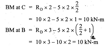
BM at C = RD × 1 = 56 × 1 = 56 kN-m
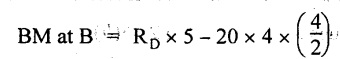
= 56 × 5 - 160 = 120 kN-m
BM at A = 0
Join all the values as shown in Fig.2.34(b).
SF is zero at x distance from D. SF equation at that point is
SFx = -56 + 20 (x - 1) = 0
x = 3.8 m from D
BM is maximum where the SF changes its sign.
Maximum BM,
= 134.48 kN-m
Result:
(i) The SFD and BMD are shown in Fig.2.34(b) & (c) respectively.
(ii) The BM is maximum at 3.6m from the point D.
Example 2.24:
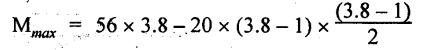
A simply supported beam of span 10m carries a concentrated load of 10 kN at 2m from the left support and a uniformly distributed load of 4 kN/m over the entire length. Sketch the shear force and bending moment diagram for the beam.
Given:
As shown in Fig.2.35(a).
To draw:
SFD and BMD.
Solution:
Taking moment about A,
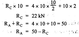
= 50 - 22 = 28 kN
SF calculation:
SF at C = = - RC =-22 kN
SF at B (without point load) = -22 + 4 × 8 = 10 kN
SF at B (with point load) SF at A = 10 + 10 = 20 kN
SF at A = RA = 28 kN
Join all the values as shown in Fig.2.35(b).
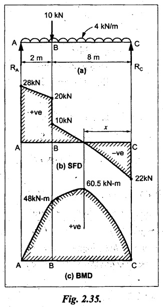
BM calculation:
BM at C = 0
BM at A = 0
The SF changes its sign at a distance of 'x' m from C.
SF equation at that point is SFx = -22 + 4 x = 0
x = 5.5 m from C

Join all the values as shown in Fig.2.35(c).
Result:
The SFD and BMD are shown in Fig.2.35(b) & (c) respectively.
Example 2.25:
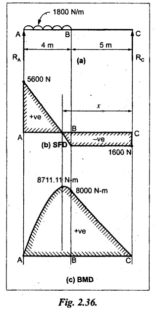
A simply supported grider 9 m long is loaded with a UDL of 1800 N per meter over a length of 4 m from the left end. Draw BM and SF diagrams for the grider and calculate the magnitude and position of the maximum BM.
Given:
As shown in Fig.2.36(a).
To draw:
SFD and BMD
Solution:
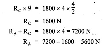
Taking moment about A,
SF calculation:
SF at C = RC = - 1600 N
SF at B = -1600 N
SF at A = RA = 5600 N
Join all the values as shown in Fig.2.36(b).
BM calculation:
BM at C = 0
BM at B = RC × 5
= 1600 × 5 = 8000 N-m
BM at A = 0
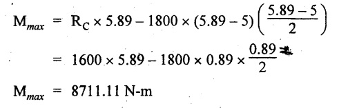
The SF changes its sign at 'x' distance from end C. SF equation at that point is,
SFx = - 1600 + 1800 (x - 5) = 0
x = 5.89 m.
BM at that point is the maximum,
Join all the values as shown in Fig.2.36(c).
Result:
(i) The SFD and BMD are shown in Fig.2.36(b) & (c) respectively.
(ii) The value of maximum BM 8711.11 N-m and is placed at 5.89 m from the end C.
Example 2.26:
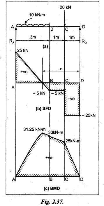
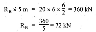
A simply supported beam of span 5m is subjected to UDL of 10 kN/m over the left 3m length. In addition it carries a downward load of 20 kN at Im from the right support. Draw the SF and BM diagrams for the beam indicating the important values.
Given:
As shown in Fig.2.37(a).
To draw:
SFD and BMD.
Solution:
Taking moment about A,
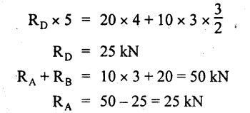
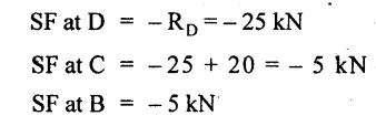
SF calculation:
SF at A = RA = 25 kN .
Join all the values as shown in Fig.2.37(b).
BM calculation:
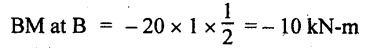
BM at D = 0
BM at C = RD × 1 = 25 × 1
= 25 kN-m
BM at B = RD × 2 - 20 × 1
= 25 × 2 - 20 = 30 kN-m
BM at A = 0
The SF changes its sign at a distance of x m from end D. SF equation at that point is,
SFx = - 25 + 20 + 10 (x − 2) = 0
x = 2.5 m from D
The maximum BM,
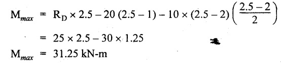
Join all BM values as shown in Fig.2.37(c).
Result:
The SFD and BMD are shown in Fig.2.37(b) & (c) respectively.
Example 2.27:
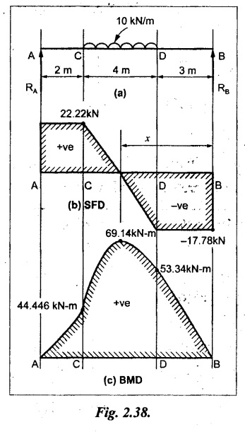
Draw the SF and BM diagrams for the beam shown in Fig. 2.38(a).
Given:
As shown in Fig.2.38(a).
To draw:
SFD and BMD.
Solution:
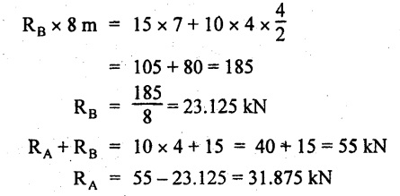
Taking moment about A,
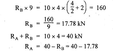
= 22.22 kN
SF calculation:
SF at B = RB = -17.78 kN
SF at D = -17.78 kN
SF at C = -17.78 + 10 × 4
= 22.22 kN
SF at A = RA = 22.22 kN
Join all the values as shown in Fig.2.38(b).
BM calculation:
BM at B = 0
BM at D = RB × 3 = 17.78 × 3 = 53.34 kN-m
BM at C = RB × 7 - 10 × 4 × 4/2 = 44.446 kN-m
BM at A = 0
Maximum BM calculation:
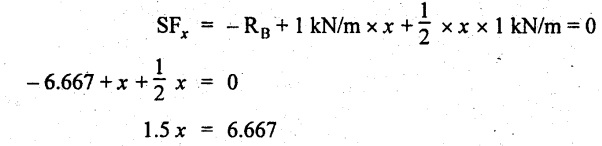
The BM is maximum when SF changes its sign. SF changes its sign at a distance of x m from end B. SF equation at that point is,
SFx = -RB + 10 × (x - 3) = 0
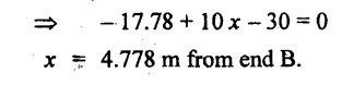
The BM is maximum at a distance of 4.778 m from end B.
The maximum BM is,
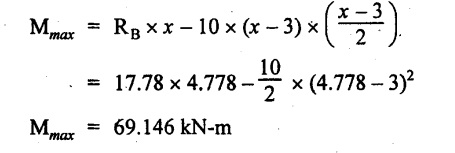
Join all the values as shown in Fig.2.38(c).
Result:
The SFD and BMD are shown in Fig.2.38(b) & (c) respectively.
Example 2.28:
Construct the shear force diagram and the ending moment diagram for the beam loaded as shown in Fig.2.39(a).
Given:
As shown in Fig.2.39(a).
To draw:
SFD and BMD.
Solution:
Taking moment about A,
SF calculation:
SF at B = -RB = -23.125 kN
SF at D = - 23.125 +15
= - 8.125 kN
SF at C = 8.125 kN
SF at A = RA = 31.875 kN
Join the SF values between AC by inclined line since the load is UDL. Refer Fig.2.39(b).
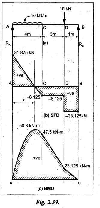
BM calculation:
BM at B = 0
BM at D = RB × 1
= 23.125 kN-m
BM at C = RB × 4 -15 × 3
= 23.125 × 4 - 45 = 47.5 kN-m
BM at A = 0
Join the BM values between C and A by parabolic curve and other by a straight line as shown in Fig.2.39(c).
The maximum BM is situated at a distance of 'x' m from the point A where the SF changes its sign. SF equation at that point is,
RA - 10 × x = 0
31.875 - 10x = 0
x = 3.1875 m
The maximum BM is acting at 3.1875m from end A or 4.8125m from end D.
Maximum BM:
Taking moment of all forces placed left of the point where the SF is zero,
Result:
The SFD and BMD are shown in Fig.2.39(b) & (c) respectively.
Example 2.29:
A beam of span 8m is supported at its ends. His loaded with a gradually varying load of 1 kN/m from left hand support to 2 kN/m to the right hand support. Construct the SFD and BMD. Also mark the salient values.
Given:
As shown in Fig.2.40(a).
To draw:
SFD and BMD
Solution:
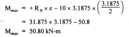
Taking moment about A,
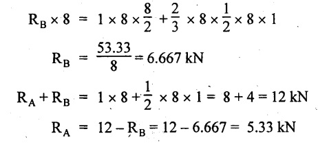
SF calculation:
SF at B = = -RB = 6.667 kN
SF at A = +RA = 5.33 KN
Join the above values by a parabolic curve as shown in Fig.2.40(b).
BM calculation:
BM at B = 0
BM at A= 0
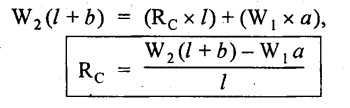
Maximum BM:
SF is zero at a point x from right end B. The SF equation is,
x = 4.4446 m
The BM is maximum at 4.4446 m from right end B.
The maximum BM is,
Join the above values by a cubic curve as shown in Fig.2.40(c).
Result:
The SFD and BMD are shown in Fig.2.40(b) & (c) respectively.
16. SFD AND BMD FOR OVERHANGING BEAMS
In overhanging beams, the ends may be extended beyond the supports either one side or both sides.
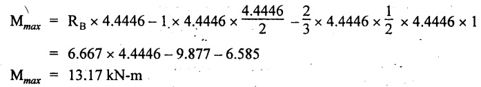
Case (a): Concentrated loads
Consider a beam ABCD, supported at B and C, and it is overhanging on both sides. Let W1 and W2 be the loads placed at the extreme left and right respectively.
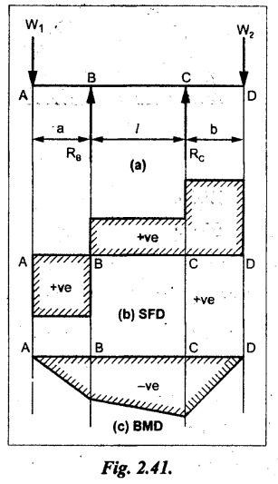
Reactions:
Taking moments about B,
We know that,
SF calculation:
SF at D = +W2 (+ve sign due to right side downward load)
SF at C = W2 - RC
SF at B = W2 - RC
(This is algebraic sum of load on right side of the beam from B)
SF at B = -W1
(This is algebraic sum of load on left side of the beam from B and -ve sign due to left side downward load)
SF at A = -W1
Connecting the above values by straight parallel or perpendicular lines for getting SFD as shown in Fig.2.41(b).
BM calculation:
Bending moment is zero at both the ends and it may vary from +ve to -ve in between the region. The point where the BM changes its sign is called point of Contraflexure or inflexion.
Taking moment about corresponding points,
BM at D = 0
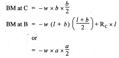
BM at C = -W2 × b
BM at B = W2 (b + 1) + RC × l
or
BM at B = -W1 × a
BM at A = 0
The above values are connected by straight inclined lines as shown in Fig.2.41(c).
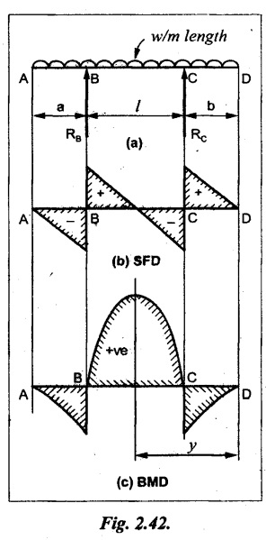
Case (b): Overhanging beam with UDL
Consider a beam ABCD supported on a span l at B and C, carrying a UDL of w per m length as shown in Fig.2.42(a).
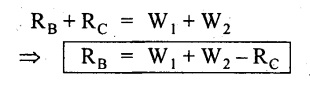
Reactions:
Taking moments about B,
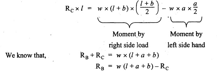
SF calculation:
SF at D = 0
SF at C (without reaction RC) = w × b
SF at C (with reaction) = w × b - RC
SF at B (without reaction RB) = w × (b + l) - RC or –w × a
SF at B (with reaction) = w × a + RB
The above values are connected by straight inclined lines because of UDL acting entire length.
BM calculation:
BM at D = 0
BM at A = 0.
Maximum BM:
Let us consider a section 'x' m from the support D, where the SF changes its sign and BM is maximum.
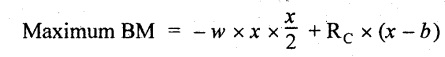
Here it should be +ve.
Connect the above values by parabolic curve since it is UDL.
Point of contraflexure:
Let y be the distance from D, where the BM changes its sign, i.e., point of Contraflexure.
Taking moment about point of contraflexure and equating it to zero,
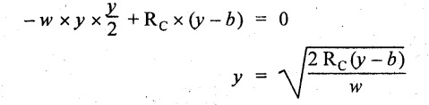
Similarly, we can calculate another point of contraflexure.
17. SOLVED PROBLEMS ON OVERHANGING BEAM
Example 2.30:
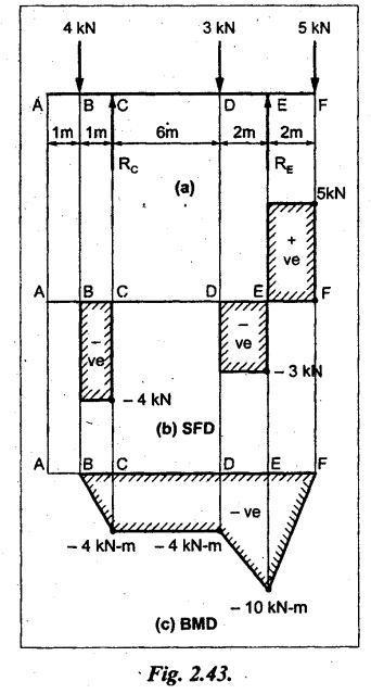
A beam 12 m long is supported at two points 2 m from each end, so that there are two equal overhanging portions. It carries concentrated loads of 4 kN, 3 kN and 5 kN at 1m, 8m and 12m respectively from the left end. Draw the SF and BM diagrams. What are the values of maximum BM and maximum SF?
Given:
As shown in Fig.2.43(a).
To draw:
(i) SFD and BMD
(ii) Maximum BM & SF
Solution:
Taking moment about C,
RE × 8 = 5 × 10 + 3 × 6 + (-4 × 1)
= 50 + 18 – 4 = 64
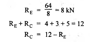
= 12 – 8 = 4 kN
SF calculation:
SF at F = 5 kN.
SF at E = 5 - RE – 5 – 8 = -3 kN
SF at D = -3 kN + 3kN = 0 kN
SF at C = 0 - RC = - 4 kN
SF at B = -4 kN + 4 kN = 0 kN
SF at A = 0 KN
SF is zero between AB and CD sections. Connect all other points as shown in Fig.2.43(b).
BM calculation:
BM at F = 0
BM at E = - 5 kN × 2 m
= - 10 kN-m
BM at D = − 5 kN × 4 m + RE × 2 m
= -20 + 8 × 2 = -4 kN-m
BM at C = -5 kN × 10 m + RE × 8 - 3 kN × 6 m
= -50 + 8 × 8 – 18 = -4 kN-m
BM at B = - 5 kN × 11 m + RE × 9 m - 3 kN × 7m + RC × 1m
= -55 + 72 – 21 + 4 = 0
BM at A = 0
Connect all the values as shown in Fig.2.43(c).
Result:
(i) SFD and BMD are shown in Fig.2.43(b) & (c).
(ii) Maximum SF = 5 kN and maximum BM = -4 kN-m.
Example 2.31:
Draw the BM and SF diagrams for the beam loaded as shown in Fig.2.44(a). What is the distance of the point of contraflexure from the right end F?
Given:
As shown in Fig.2.44(a).
To draw:
(i) SFD and BMD
(ii) Point of contraflexure
Solution:
Taking moment about B,
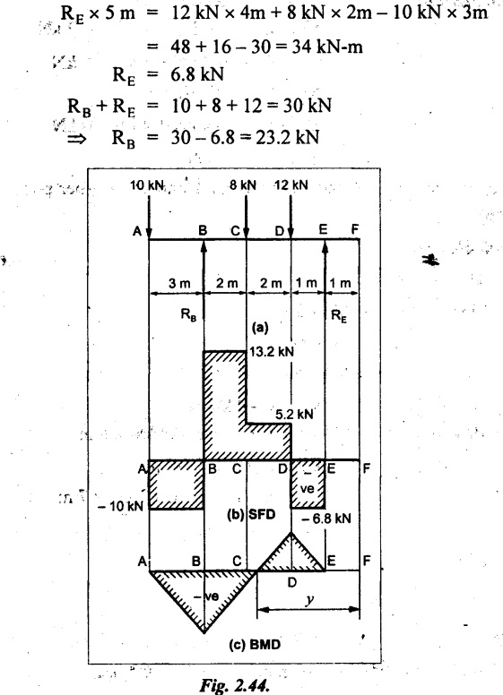
SF calculation:
SF at F = 0
SF at E = - RE = - 6.8 kN
SF at D = -6.8 + 12 = 5.2 kN
SF at C = 5.2 + 8 = 13.2 kN
SF at B = 13.2 - RB
= 13.2 - 23.2 = - 10 kN
SF at A = -10 kN
Connect all the values by straight lines as shown in Fig.2.44(b).
BM calculation:
BM at F = 0
BM at E = 0
BM at D = RE × 1 m = 6.8 kN-m.
BM at C = RE × 3 m - 12 kN × 2m
= 6.8 × 3 – 24 = - 3.6 kN-m
BM at B = RE × 5 m - 12 kN × 4 m - 8 × 2 m
= 6.8 × 5 – 48 – 16 = -30 kN-m
BM at A = 0
Point of contraflexure
Consider the point y distance from right end. Taking moment about that point and equating it to zero.
RE × (y - 1) - 12 (y − 2) = 0
6.8y - 6.8 - 12 y +24 = 0
y = 3.3 m
The point of contraflexure occurs at a distance of 3.3 m from right end.
Result:
(i) SFD and BMD are shown in Fig.2.44(b) & (c) respectively.
(ii) Point of contraflexure occurs at a distance of 3.3m from right end.
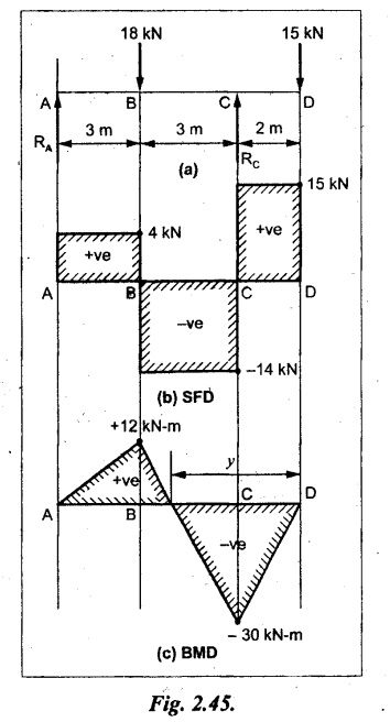
Example 2.32:
A beam of total length 8m is freely supported at the left end and at a point 6m from right end. It carries two point loads of 15 kN and 18 kN, in which one is at the free end and other is 3m from the left support. Draw the SF and BM diagram. Locate the point of contraflexure.
Given:
As shown in Fig.2.45(a).
To draw:
SFD and BMD
Solution:
Taking moment about A,
RC × 6m = 15 kN × 8 m + 18 kN × 3 m
= 120 + 54
= 174 kN-m
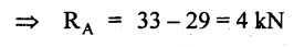
RC = 29 kN
RA + RC = 18 + 15 = 33 kN
SF calculation:
SF at D = 15 kN
SF at C = 15 kN - RC
= 15 kN – 29 = -14 kN
SF at B = -14 kN + 18 kN = 4 KN
SF at A = RA = 4 kN
The above values are connected by straight lines as shown in Fig.2:45(b).
BM calculation:
BM at D = 0
BM at C = - 15 kN × 2 m
= - 30 kN-m
BM at B = - 15 kN × 5 m + RC × 3 m
= -75 + 29 × 3 = 12 kN-m
BM at A = 0
Connecting the above values by straight inclined lines as shown in Fig.2.28(c). The BM changes its sign at y distance from the right end. (i.e., Point of contraflexure).
Taking moment about point of contraflexure,
- 15 kN × y m+ RC (y - 2) m = 0
-15y + RCy - 2 RC = 0
-15y + 29 y - 2 × 29 = 0
y = 4.143 m
The point of contraflexure occurs at 4.143m from the right end.
Result:
(i) SFD and BMD are shown in Fig.2.45(b) & (c) respectively.
(ii) Point of contraflexure occurs at 4.143m from the right end.
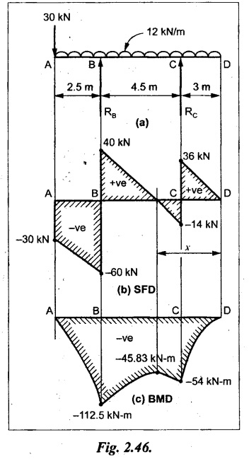
Example 2.33:
A horizontal beam AD, 10m long carries a UDL of 12 kN/m length run together with a concentrated load 30 kN at the left end A. The beam is supported at a point B which is 2.5m from A and C which is in the right hand half of the beam and 3m from D. Plot the SF and BM diagrams.
Given:
As shown in Fig.2.46(a).
To draw:
SFD and BMD.
Solution:
Taking moment about B,
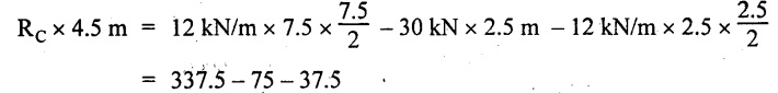
= 225 kN-m
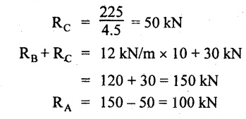
SF calculation:
SF at D = 0
SF at C (without reaction RC)
= 12 × 3 = 36 kN
SF at C (with reaction RC)
= 36 kN - RC = 36 – 50 = -14 kN
SF at B (without reaction RB)
= -14 kN + 12 kN/m × 4.5 = 40 KN
SF at B (with reaction RB)
= 40 kN - RB = 40 - 100 = - 60 kN
SF at A = - 30 kN
Connect all the values by straight lines as shown in Fig.2.46(b).
BM calculation:
BM at D = 0
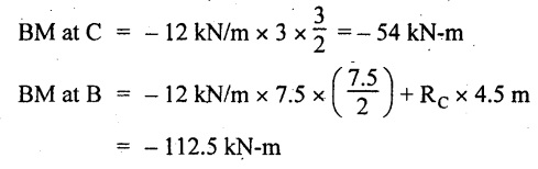
BM at A = 0
In SFD, the SF changes its sign between B and C. At that point the BM will be maximum. Consider the point x m from the right support where the SF changes its sign. SF at that point is,
12 kN/m × x m - RC = 0
12 x = RC
The maximum BM is occurs at 4.166m from right end.
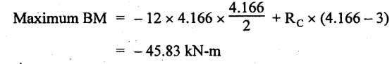
Join all the values by parabolic curves as shown in Fig.2.46(c).
Result:
The SFD and BMD are shown in Fig.2.46(b) & (c) respectively.
Example 2.34:
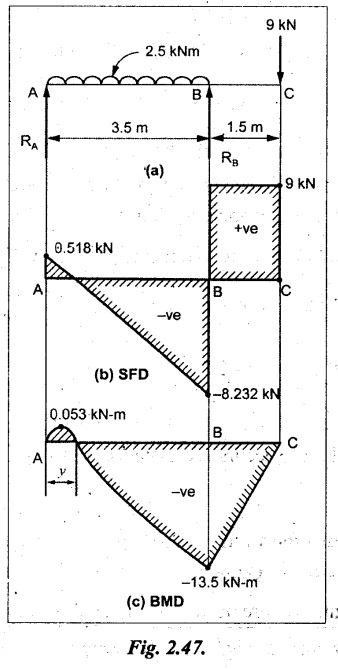
A beam of 5m length is hinged at one end and freely supported at a distance of 3.5m from the hinge. It carries a uniformly distributed. load of 2.5 kN/m between hinged end and support and a point load of 9 kN at the free end. Construct the SF and BM diagrams. Find out the maximum bending moment and location of point of contraflexure.
Given:
As shown in Fig.2.47(a).
To draw:
(i) SFD and BMD
(ii) Maximum BM
(iii) Location of point of contraflexure
Solution:
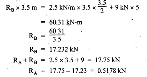
Taking moment about A,
SF calculation
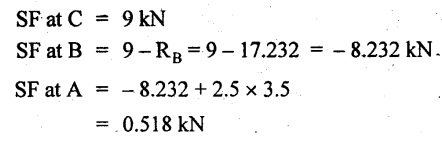
The above values between C & B are connected by straight parallel lines and between A & B by a straight inclined line as shown in Fig.2.47(b).
BM calculation:
BM at C = 0
BM at B = 9 kN × 1.5 m = -13.5 kN-m
BM at A = 0
From SFD, the SF changes its sign between A & B, consider x is the distance from the left support. SF at that point is
RA - 2.5 kN/m × x = 0
0.5178 - 2.5 x = 0
x = 0.207 m
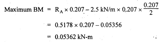
⸫ The maximum BM occurs at 0.207 m from left support. Taking moment of all forces about that point to the left side,
The point of contraflexure occurs at y m from the left end between A & B. Taking moment about that point and equating it to zero.
Taking moment of all forces placed left side of that point,
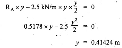
The point of contraflexure occurs at a distance of 0.41424 m from left end.
Result:
(i) SFD and BMD are shown in Fig.2.47(b)&(c) respectively.
(ii) Maximum BM = 0.053 kN-m.
(iii) The point of contraflexure occurs at a distance of 0.41424 m from left end.
Example 2.35:
A beam 7.5m long, has supports 5m apart, there being an overhang of Im on the left and 1.5m on the right. There is a point load of 5 kN at each free end, a UDL of 8 kN/m over the supported length and 4 kN/m over the overhanging portion on the right. Construct the SF and BM diagrams.
Given:
As shown in Fig.2.48(a).
To draw:
SFD and BMD.
Solution:
Taking moment about B,
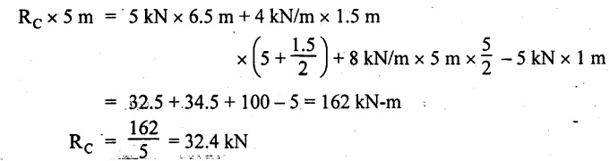
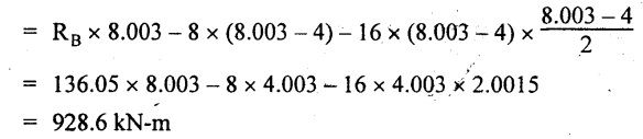
RB + RC = 5 kN + 5 kN + 8 × 5m + 4 × 1.5 m
= 5 + 5 + 40 + 6 = 56 kN
RB = 56 - 32.4 = 23.6 kN
SF calculation:
SF at D = 5 kN
SF at C (without reaction RC)
= - 5 kN + 4 × 1.5 = 11 kN
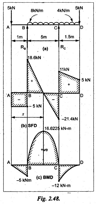
SF at C (with reaction RC)
= 11 kN - RC = 11 - 32.4 = - 21.4 kN
SF at B (without reaction RB)
= -21.4 + 8 kN/m × 5 m
= -21.4 + 40 = 18.6 kN
SF at B (with reaction RB)
= 18.6 - RB
= 18.6 - 23.6 = - 5 kN
SF at A = -5 kN
The above values are connected as shown in Fig.2.48(b).
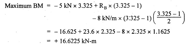
BM calculation:
BM at D = 0
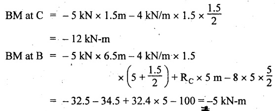
BM at A = 0
The maximum BM occurs at a distance of x m from left end as shown in Fig.2.31(b). i.e., between B and C. The SF equation for that point is,
-5 + RB - 8 kN/m × (x - 1) m = 0
-5 + 23.6 - 8x + 8 = 0
x = 3.325 m
⸫ The maximum BM occurs at 3.325 m from the left end.
Taking moment of all forces about the point where SF changes its sign from the left side.
Join all the BM values as shown in Fig.2.48(c).
Result:
SFD and BMD are shown in Fig.2.48(b) & (c) respectively.
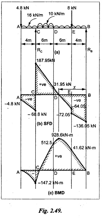
Example 2.36:
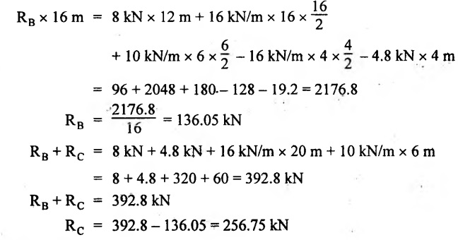
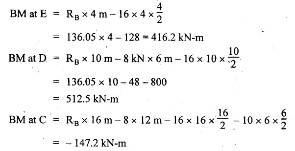
A beam AB, 20 m long is supported at the right hand end B and at an intermediate point C, 4m from A so that BC 16m. It carries two concentrated loads, one of 4.8 kN at A and another of 8 kN at E which is at a distance of 4m from B. In addition, the beam carries a UDL of 16 kN/m run over its entire length and also another of 10 kN/m run over the length CD, where CD 6m and BD = 10m. Draw the diagram of BM and SF for the beam.
Given:
As shown in Fig.2.49(a).
To draw:
SFD and BMD.
Solution:
Taking moment about C,
SF calculation:
SF at B = -RB = - 136.05 kN
SF at E (without point load)
= -RB + 16 kN/m × 4 m
= -136.05 + 64 = -72.05 kN
SF at E (with point load)
= -72.05 kN + 8 = -64.05 kN
SF at D = 64.05 kN + 16 × 631.95 KN
SF at C (without reaction RC)
= 31.95 + 16 × 6 + 10 × 6
= 187.95 kN
SF at C (with reaction RC)
= 187.95 - RC
= 187.95 - 256.75 = -68.8 kN
SF at A = -4.8 kN
Connect all the above values as shown in Fig.2.49(b).
BM calculation:
BM at B = 0.
BM at A = 0
The BM is maximum at a distance of x m from right support between DE. [Refer SFD Fig.2.49(b)]. SF equation for that point is,
-RB + 8 kN + 16 kN/m × x m = 0
- 136.05 + 8 + 16x = 0
x = 8.003 m
The BM is maximum at 8.003 m from right support. Taking moment of all forces placed right side of that point,
Maximum BM,
Connect all the values by parabolic curve as shown in Fig.2.49(c).
Result:
SFD and BMD are shown in Fig.2.49(b) & (c) respectively.
Example 2.37:
Draw the SF and BM diagrams for the beam loaded as shown in Fig. 2.50(a).
Given:
As shown in Fig.2.50(a).
To draw:
SFD & BMD
Solution:
Taking moment about B,
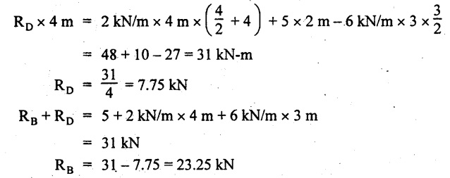
SF calculation:
SF at E = 0
SF at D (without reaction RD)
= 2 × 4 = 8 kN
SF at D (with reaction RD)
= 8 kN - RD = 8 - 7.75 = 0.25 kN
SF at C = 0.25 kN + 5 kN
= 5.25 kN
SF at B (without reaction RB)
= 5.25 kN
SF at B (with reaction RB)
= 5.25 - RB = 5.25 - 23.25 = -18kN
SF at A = 0
BM calculation:
BM at E = 0
BM at A = 0
Draw the bending moment diagram as shown in Fig.2.50(c).
The values between DE and AB are connected by parabolic curves since the UDL is acting over the section. The values between BC and CD are connected by straight inclined lines.
Result:
SFD and BMD are shown in Fig.2.50(b) & (c) respectively.
Example 2.38:
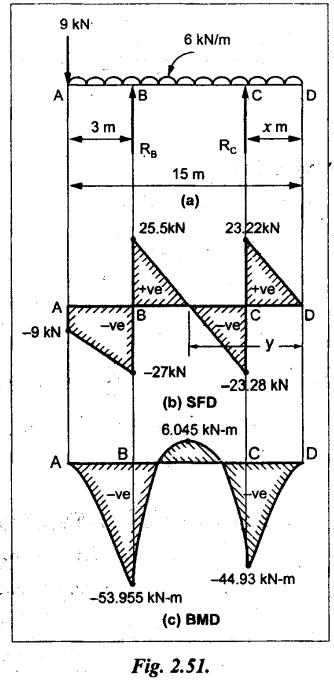
A horizontal beam AD 15m long carries a UDL of 6 kN/m run together with a concentrated load of 9 kN at the left end A. The beam is supported at a point B which is 3 m from A and at C which is in the right hand half of the beam and x m from D. Determine the value of x, if the mid point of the beam is the point of contraflexure. Plot the SF and BM diagrams.
Given:
As shown in Fig.2.51(a).
To find:
(i) 'x' m from D.
(ii) Draw SFD & BMD.
Solution:
In the problem, it is given that the point of contraflexure occurs at midpoint of the beam i.e., 7.5 m from both the end. At that point BM is zero or changes its sign.
Taking moment of all forces placed left side of the midpoint,
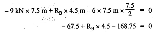
RB = 52.5 kN
RB + RC = 6 × 15 m + 9 kN = 99 kN
RC = 99 - 52.5 = 46.5 kN
Now, taking moment of all forces placed right side of the midpoint and equating it to zero.
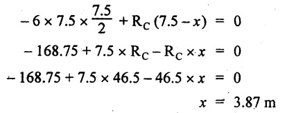
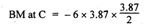
The support C is placed 3.87 m from right end of the beam.
SF calculation:
SF at D = 0
SF at C (without reaction RC)
= 6 kN × 3.87 m = 23.22 kN
SF at C (with reaction RC)
= 23.22 - RC
= 23.22 - 46.5 = -23.28 kN
SF at B (without reaction RB)
= 6 × 12 m - RC = 72 - 46.5
= 25.5 kN
SF at B (with reaction RB)
= 25.5 - RB
= 25.5 - 52.5 = -27 kN
SF at A = -9 kN
Draw the SF diagram as shown in Fig.2.51(b).
BM calculation:
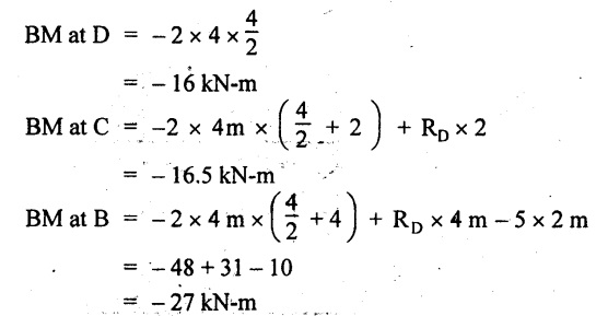
BM at D = 0
= -44.93 kN-m
BM at A = 0
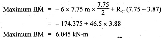
Consider the maximum BM occurs at a point y m from the right end where the SF changes its sign.
SF equation at that point is,
6 × y - RC = 0
6y - 46.5 = 0
y = 7.75 m
The maximum BM occurs at 7.75 m from the right end.
Connect all the values by parabolic curves as shown in Fig.2.51(c).
Result:
(i) The distance of support 'C' from right end is 3.87 m.
(ii) SFD and BMD are shown in Fig.2.51(b) & (c) respectively.
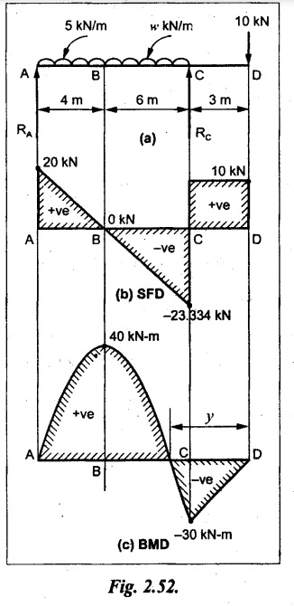
Example 2.39:
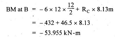
A beam 13 m long is loaded as shown in Fig.2.52(a). If the shear force at B is zero, what must be the intensity of loading in kN/m run between B and C? Sketch the SF and BM diagrams.
Given:
As shown in Fig.2.52(a).
To find:
(i) Intensity of loading between B & C.
(ii) Draw SFD & BMD.
Solution:
In the problem, it is given that SF is zero at point B, therefore write the SF equation and equating it to zero.

Taking moment about A,
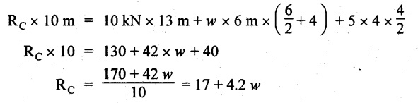
Substituting RC value in equation (1),
10 – 17 - 4.2 w + 6w = 0
⇒ 1.8 w = 7
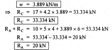
SF calculation:
SF at D = 10 kN
SF at C = 10 - RC = 10 - 33.334
= -23.334 kN
SF at B = 0 (⸪ Given)
SF at A = + RA = + 20 kN
The above values are connected as shown in Fig.2.52(b).
BM calculation:
BM at D= 0
BM at C = 10 × 3 m = - 30 kNm
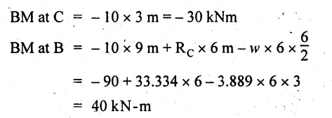
BM at A= 0
Draw the BM as shown in Fig.2.52(c).
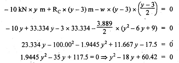
Point of contraflexure
Taking moment of all forces placed right side of the point of contraflexure which is situated at y m from right support.
Join the SF values as shown in Fig.2.53(b).
BM calculation:
BM at C = 0
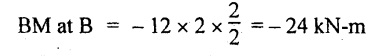
BM at B = -4 × 2 = -8 kN-m
BM at A = 0
Join the values as shown in Fig.2.53(c).
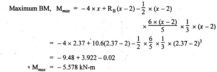
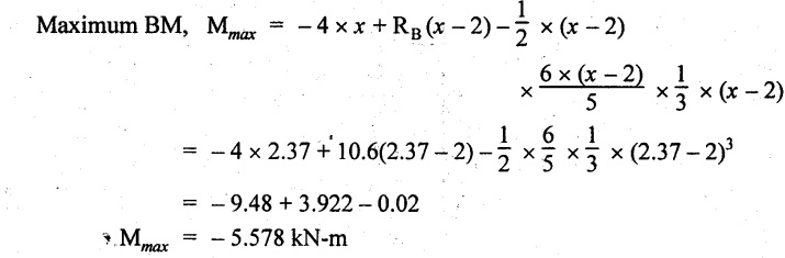
Maximum BM calculation
The SF is zero at a distance of 'x' m from the end C. The SF equation at that point is
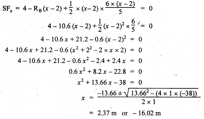
-ve value is not possible. Therefore x = 2.37 m from C.
Result:
The SFD and BMD are shown in Fig.2.53(b) & (c) respectively.
Example 2.41:
A beam of length 11 m is simply supported at two supports which are 4m apart, with overhangs of 4m on the right and 3m on the left side respectively as shown in Fig.2.54(a). The beam carries a UVL of 12 kN/m on the right overhang side, a UDL of 15 kN/m on the left overhang side and a concentrated load of 20 kN at midspan of the simply supported beam. Draw SFD and BMD.
Given:
As shown in Fig.2.54(a).
To Draw:
SFD & BMD
Solution:
Taking moment about B,
-ve value is not possible. Therefore x = 2.37 m from C.
Result:
The SFD and BMD are shown in Fig.2.53(b) & (c) respectively.
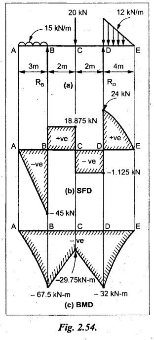
Example 2.41:
A beam of length 11 m is simply supported at two supports which are 4m apart, with overhangs of 4m on the right and 3m on the left side respectively as shown in Fig.2.54(a). The beam carries a UVL of 12 kN/m on the right overhang side, a UDL of 15 kN/m on the left overhang side and a concentrated load of 20 kN at midspan of the simply supported beam. Draw SFD and BMD.
Given:
As shown in Fig.2.54(a).
To Draw:
SFD & BMD
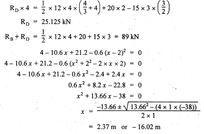
Solution:
Taking moment about B,
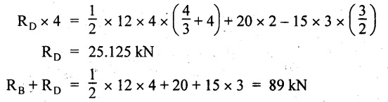
⇒ RB = 89 - 25.125 kN
⇒ RB = 63.875 kN
SF calculation:
SF at E = 0
SF at D (without reaction)
SF at D (with reaction)
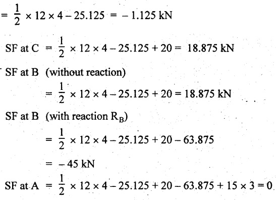
Join all the values as shown in Fig.2.54(b).
BM calculation:
BM at E = 0
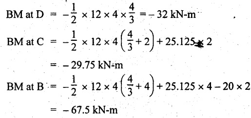
BM at A = 0
⸫ The maximum BM will occur at C of -29.75 kN-m.
Join all the values as shown in Fig.2.54(c).
Result:
The SFD and BMD are shown in Fig.2.54(b) & (c) respectively.
university solved problems on overhanging beam: Transverse Loading on Beams and Stresses in Beam - Strength of Materials
UNIVERSITY SOLVED PROBLEMS ON OVERHANGING BEAM
Example 2.42:
Draw the shear force and bending moment diagrams for the beam shown in Fig. 2.55(a) indicating principle values.
Given:
As shown in Fig.2.55(a).
To draw:
SFD and BMD
Solution:
Taking moment about A,

SF calculation:
SF at D = 0
SF at C (without reaction RC)
SF at C (with reaction RC)
= 6.25 - RC = 6.25 - 61.9 = - 55.65 kN
SF at B (without point load)
= −55.65 + 10 × 2 = - 35.65 kN
SF at B (with point load)
= -35.65 + 20 = 15.65 kN
SF at A = RA = 44.35 kN
Join the values CD by parabolic curve and all other values by inclined straight lines as shown in Fig.2.55(b).
BM calculation:
BM at D = 0
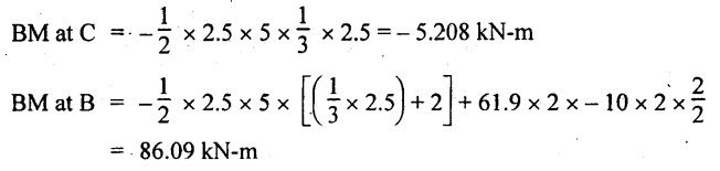
BM at A = 0
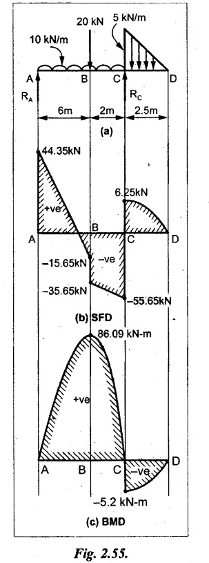
Join all the values AB and C by parabolic curves and CD by a cubic curves as shown in Fig.2.55(c).
Result:
The SFD and BMD are shown in Fig.2.55(b) & (c) respectively.
Example 2.43:
Draw the shear force and bending moment diagrams for the beam loaded as shown, locate the point of contraflexure and find the maximum and minimum values of BM.
Given:
As shown in Fig.2.56(a).

To find:
(i) Draw SFD and BMD.
(ii) Find the maximum and minimum of BM.
Solution:
Taking moment about B,

RC = 33.375 kN
RB + RC = 6 × 13 = 78 kN
RB = 78 - 33.375 = 44.625 kN
SF calculation:
SF at D = 0
SF at C
(without reaction RC)
= 6 × 2 = 12 kN
SF at C (with reaction RC)
= 6 × 2 -33.375 = -21.375 kN
SF at B (without reaction RB)
= 6 × 10 - 33.375 = 26.625 kN
SF at B (with reaction RB)
= 6 × 10 - 33.375 - 44.625
= -18 kN
SF at A = 6 × 13 - 33.375 - 44.625 = 0
Join all the values as shown in Fig.2.56(b).
BM calculation:
BM at D = 0
BM at A = 0
Maximum BM calculation:
Taking the SF at a distance 'x' m from D.
SFx = 6 × x - 33.375 = 0
x = 5.5625 m from D
Maximum BM:

Join all the values by parabolic curves as shown in Fig.2.56(c).
Result:
The SFD and BMD are shown in Fig.2.56(b) & (c) respectively.
Minimum value of BM = 0
Maximum value of BM = 26.07 kN-m
Example 2.44:
Draw the SF and BM diagrams for the beam shown below, Find the maximum values and their positions. Give the values at important points in the diagram.
Given:
As shown in Fig.2.57(a).
To draw:
(i) SFD and BMD
(ii) Maximum BM

Solution:
Taking moment about A,
RA + RB = 2 × 6 + 2 = 14 kN
RA = 14 - RB = 14 - RB = 14 - 12 = 2 kN
SF calculation
SF at C = 2 kN
SF at B (without Reaction RB) = 2 +2 × 2 = 6 kN
SF at B (with Reaction RB) = 6 - RB
= 6 – 12 = -6 kN
SF at A = RA = 2 kN
Join all the values as shown in Fig.2.57(b).
BM calculation:
BM at C = 0
BM at A = 0
Maximum BM calculation:
Taking SF at a distance 'x' m from C
SFx = 2 – 12 + 2 × x = 0
-10 + 2 x = 0
⇒ 2x = 10
x = 5 m from C
Maximum BM:

Join all BM values as shown in Fig.2.57(c).
Result:
The SFD and BMD are shown in Fig.2.57(b) & (c) respectively.
The maximum BM 1 KN-m occurs at a distance of 5 m from end C.
Example 2.45:
Draw the shear force and bending moment diagram for the loaded beam shown in Fig.2.58(a).
Given:
As shown in Fig.2.58(a).

To draw:
SFD and BMD
Solution:
Taking moment about A,
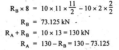
= 56.875 kN
SF calculation:
SF at D = 0
SF at B (without reaction RB)
= 10 × 3 = 30 kN
SF at B (with reaction RB)
= 30 - 73.125 = - 43.125 kN
SF at A (without reaction RA)
= 10 × 11 - 73.125 = 36.875 kN
SF at A (with reaction RA)
= 36.875 - 56.875 = - 20 kN
SF at C = 0
Join all the values as shown in Fig.2.58(b).
BM calculation:
BM at D = 0
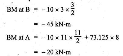
BM at C = 0
Maximum BM calculation:
SF equation where it changes sign. (i.e., x m from the end D),
SFx = 10 × x - RB
10 × x - 73.125 = 0
x = 7.3125 m
Therefore,

= 47.988 KN-m
Join all the BM values as shown in Fig.2.58(c).
Result:
The SFD and BMD are shown in Fig.2.58(b) & (c).
Example 2.46:
A beam 6m long rests on supports 5m apart, the right hand end is overhanging by Im. The beam carries a UDL of 20 kN/m over the entire length of the beam. Draw SFD and BMD indicating the maximum BM and the point of contraflexure.
Given:
As shown in Fig.2.59(a).

To draw:
(i) SFD and BMD
(ii) Mmax and Point of contraflexure
Solution:
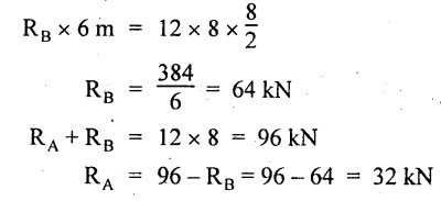
Taking moment about A,
RA + RB = 20 × 6 = 120 kN
RA = 120 - RB = 120 - 72 = 48 kN
SF calculation:
SF at C = 0
SF at B (without reaction RB)
= 20 × 1 = 20 kN
SF at B (with reaction RB)
= 20 – 72 = -52 kN
SF at A = RA = 48 kN
Join all the values as shown in Fig.2.59(b).
BM calculation:
BM at C = 0
BM at A = 0
Maximum BM:
Consider the distance x m from C where the SF changes its sign.
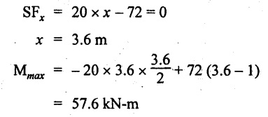
Join all BM values as shown in Fig.2.59(c).
Point of contraflexure:
Point of contraflexure is the point where BM is zero. Consider the point which is distance from C Where BM is zero.
Taking moment about that point,
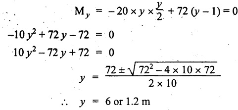
y = 6 is not a possible value.
⸫ The point of contraflexure is 1.2m from C.
Result:
(i) The SFD and BMD are shown in Fig.2.59(b) & (c) respectively.
(ii) Maximum value of BM = 57.6 kN-m
(iii) The point of contraflexure occurs at a distance of 1.2 m from end C.
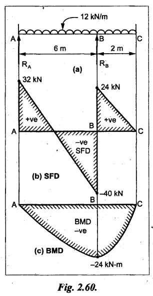
Example 2.47:
Draw the SFD and BMD for the beam loaded as shown in Fig. 2.60.
Given:
As shown in Fig.2.60(a).
To draw:
SFD and BMD
Solution:
Taking moment about A,
SF calculation:
SF at C = 0
SF at B (without reaction RB)
= 12 × 2 = 24 kN
SF at B (with reaction RB)
= 12 × 2 - RB
= 24 - 64 = -40 kN
SF at A= +RA = +32 kN
Join all the SF values by inclined line as shown in Fig.2.60(b).
BM calculation:
BM at C = 0
BM at A = 0
Join the above BM values by parabolic curve as shown in Fig.2.60(c).
Result:
The SFD and BMD are shown in Fig.2.60(b) & (c).
Example 2.48:
Construct the SFD and BMD for the beam shown in Fig. 2.61(a).
Given:
As shown in Fig.2.61(a).
To draw:
SFD and BMD
Solution:
Taking moment about A,

= 6 + 30 + 25 = 61
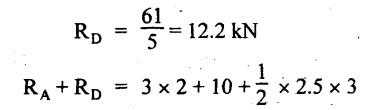
= 6 + 10 + 3.75 = 19.75 KN
RA = 19.75 - RD = 19.75 - 12.2
RA = 7.55 kN

SF calculation:
SF at E = 0
SF at D (without reaction)
SF at D (with reaction RD)
= 3.75 - RD = 3.75 - 12.2
= - 8.45 kN
SF at C = -8.45 + 10 = 1.55 kN
SF at B = 1.55 kN
SF at A = RA = 7.55 kN
Connect the values between D and E by parabolic curve and all other values are joined as shown in Fig.2.61(b).
BM calculation:
BM at E = 0
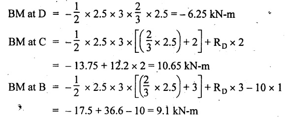
BM at A = 0
Join the values between C and E by cubic curve and AB by parabolic curve as shown in Fig.2.61(c).
Result:
The SFD and BMD are drawn as shown in Fig.2.61(b) & (c) respectively.
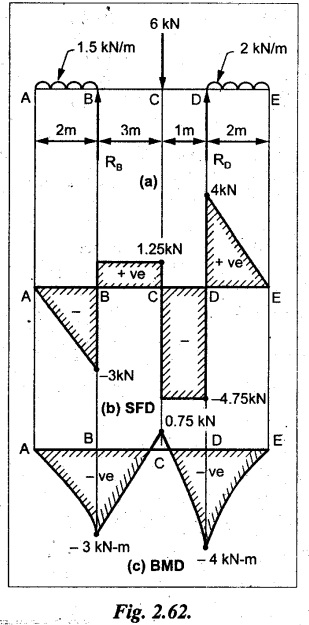
Example 2.49:
Draw the SFD and BMD for the beam shown in Fig. 2.62(a).
Given:
As shown in Fig.2.62(a).
To draw:
SFD and BMD
Solution:
Taking moment about B,
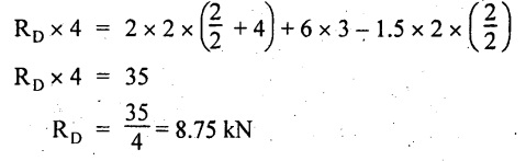
RB + RD = 1.5 × 2 + 2 × 2 + 6 = 13 kN
RB = 13 - RD = 13 - 8.75 = 4.25 kN
SF calculation:
SF at E = 0
SF at D (without reaction RD) 2 × 2 = 4 kN
SF at D (with reaction RD)
= 4 - RD = 4 - 8.75 = -4.75 kN
SF at C = -4.75 + 6 = 1.25 kN
SF at B (without reaction RB) = -4.75 + 6 = 1.25 kN
SF at B (with reaction RB) = 1.25 - RB
= 1.25 - 4.25 = -3 kN
SF at A = 0
Join all SF values as shown in Fig.2.62(b).
BM calculation:
BM at E = 0
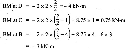
BM at A = 0
Join all the BM values as shown in Fig.2.62(c).
Result:
The SFD and BMD are as shown in Fig.2.62(b) & (c) respectively.
No comments:
Post a Comment