Problems for Practice: Transverse Loading on Beams and Stresses in Beam - Strength of Materials
PROBLEMS FOR PRACTICE
For cantilever beams
1. A cantilever beam of length 1.5m carries a point load of 3 kN at its free end and another load of 2 kN at a distance of 1m from the fixed end. Draw the SF and BM diagrams for the cantilever.
2. A cantilever beam of length 5m carries point loads of 3 kN, 4 kN and 6 kN at 0, 2 and 3.5m from the free end. Draw the SFD and BMD for the cantilever.
3. A cantilever of length 4m carries a UDL of 3 kN/m over the whole length. Draw the SFD and BMD.
4. A cantilever of length 2m carries a uniformly distributed load of 3 kN/m over a length of 1m from the fixed end. Draw the SFD and BMD.
5. A cantilever of length 1.5m carries a UDL of 4 kN/m run over a length 1 m from the free end. Draw the SFD and BMD.
6. A cantilever of length 2.5m carries a UDL of 2 kN/m over the whole length and a point of 3 kN at the free end. Draw the SF and BM diagrams. If the point load of the same 3 kN acts at a distance of 1m from the fixed. Draw the SF and BM diagram for the cantilever with same UDL.
7. A cantilever of 3m long is loaded with a UDL of 3 kN/m run over a length of 1.5m from the free end. It also carries a point load of 3 kN at a distance of 1 m from the free end. Draw the SFD and BMD.
8. A cantilever of length 6m carries two point loads of 3 kN and 4 kN at a distance of 1m and 6m from the fixed end respectively. In addition to this, the beam also carries a UDL of 3 kN/m over a length of 2m at a distance of 3m from the fixed end. Draw the SFD and BMD.
9. A beam is loaded as shown in Fig. Draw the SFD and BMD.

10. A cantilever of length 6m carries a gradually varying load, zero at the free end to 3 kN/m at the fixed end. Draw the SF and BM diagrams,
For Simply supported beams:
11. Draw SF and BM diagrams for a cantilever beam 2m long carrying a gradually varying load from zero at the free end to 2000 N/m at the fixed end.
12. A SS beam of 5m long supported at the ends carries point loads of 140 kN, 60 KN and 80 kN at distances 0.5m, 2.5m and 3.5m respectively from the left support. Find the maximum, SF and BM diagrams and find maximum BM.
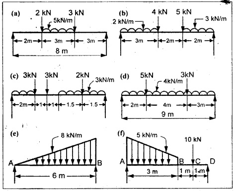
13. A simply supported beam of 4m span carries a uniformly distributed load of 3 kN/m over the whole length of the beam. Draw SF and BM diagrams.
14. A simply supported beam of 6m long is carrying a uniformly distributed load of 2 kN/m over a length of 3m from the right support. Draw the SF and BM diagrams for the beam and also calculate the maximum BM on the section.
15. Draw the SF and BM diagrams for a SSB of 8m and carrying a uniformly distributed load of 10 kN/m for a distance of 5m from the left support. Also calculate the max. BM on the section.
16. Draw the SF and BM diagrams for the following SSB and also calculate maximum BM.
For overhanging beams:
17. A beam 10m long, supported over a span of 7m and having equal overhanging on both the sides, carries a concentrated load of 20 kN at one end and another concentrated load of 40 kN at the other end. Draw the SF and BM diagrams.
18. A beam ABCDE, 14m long, cantilevered over the portion AB 6m long, supported at points B and E, BE = 8m long, carries a concentrated load at end A, 3 tones at C, 3m from B and 5 tones at D, 2m from E. In addition it carries a UDL of 3 ton/m over the portion CD. Draw the SF and BM diagrams. Determine the position of point of contraflexure.
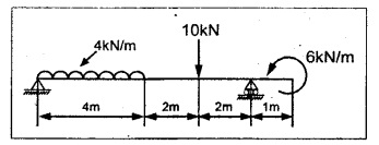
19. Draw the SF and BM diagrams of the beam shown in Fig. Show the location and magnitude of maximum bending moment.

20. Draw the SFD and BMD for the beam shown in the Figure and locate the point of contraflexure if any.

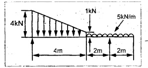
21. Draw the SF and BM diagram for the beam shown in Fig.
22. A horizontal beam AD, 8m long carries a UDL of 3 kN/m together with a concentrated load of 5 kN at the left end A. The beam is supported at a point B which is 2m from A and at C which is in the right hand half of the beam and 'x' m from D. Determine the value of x, if the midpoint of the beam is the point of contraflexure. Plot the SF and BM diagrams.
23. Draw to a convenient scale the diagrams of BM and SF for the beam supported and loaded as shown in sketch below. Show all principal values of BM and SF on the diagrams,
24. A horizontal beam simply supported by 5m length and overhang at the left end by 2.5m carries a UDL of 8 kN/m between the supports. Counter clockwise moment of 9 kN/m is applied at the left end. Draw the BMD and SFD and find
(i) the reaction at the supports.
(ii) the position and magnitude of greatest bending moment.
Problems for Practice: Transverse Loading on Beams and Stresses in Beam - Strength of Materials
PROBLEMS FOR PRACTICE
Theory of simple bending
1. A beam is freely supported at a distance of 16m apart carries a uniformly distributed load of 25 kN/m and also carries a point load of 15 kN at 6m from the left support. Calculate the maximum bending moment, if the permissible stress in timber is 60 Mpa, design a suitable rectangular section by making the depth twice the width.
2. A beam of symmetrical section has a depth of 55 mm and a moment of inertia of 8000 cm4 about its axis of bending. Calculate the length of the beam if, simply supported at the ends, it has to carry a UDL of 8 kN/m without exceeding a bending stress of 120 N/mm2.
3. A mild steel cantilever 35 mm wide and 20 mm deep is fixed at one end in a wall. The overhanging length is 4m. At the free end is applied a clockwise moment of 65 × 106 N-mm. Determine the radius to which the cantilever will bend. Find also the vertical displacement of the free end. Assume E = 2 × 10⁵ N/mm2.
4. A beam 42 mm × 60 mm of symmetrical section simply supported over a span of 6m. Calculate (a) the uniformly supported load it may carry, (b) the concentrated load it may carry at the centre, if the maximum bending stress is not exceed 25 N/mm2.
5. A 150 mm × 100 mm rolled steel joist of I-section has flanges 15mm and web 10 mm thick. It is simply supported over a length of 5m. Determine the total load uniformly distributed on the entire span that the beam could carry in addition to a concentrated load of 8 kN at its centre in order that the extreme fibre stress is limited to 19.5 N/mm2.
6. A boiler shell has a MS pipe of 200 mm diameter and 4 mm thickness simply supported freely at two points 8m apart. Find the maximum stress in the pipe when it is running full. Take unit weight of MS as 92 kN/m3 and that of water 10 kN/m2.
7. A steel tube 175 mm outer diameter and 140 mm inside diameter is used as a simply supported beam on a span of 7.5m, and it is found that the maximum safe load it can carry at mid span is 80 N/mm2. Four of these tubes are placed parallel to one another and firmly fixed together to form in effect a single beam, the centers of the tubes forming a square of 175 mm side with one pair of centers vertically over the other pair. Find the maximum central load which this beam can carry if the maximum stress is not to exceed is not to exceed twice that of single tube.
8. A cast iron T section of length 5m is used as a cantilever. The top horizontal flange of the T is 60 mm × 10 mm and the vertical leg is 8 mm × 50 mm. If the tensile stress is not to exceed 30 Mpa and the compressive stress is not to exceed 50 Mpa, determine UDL at the cantilever can carry.
9. A composite beam consists of a timber joist 100 mm deep × 75 mm wide with a steel plate 75 mm × 10 mm bolted on each side, the steel plates being symmetric about the axis of bending. If the stresses in the timber and steel are not to exceed 12 Mpa and 90 Mpa respectively, find the maximum bending moment the beam will carry and the maximum stresses in the two materials when carrying this moment. Compare the value of this moment with that of the timber joist alone. Esteel = 210 Gpa and Etimber = 15 Gpa.
10. A flitched timber beam consists of two joists 90 mm deep and 60 mm wide with a steel plate 80 mm deep and 15 mm thick placed symmetrically between and clamped to them. It is freely supported over a span of 4m and carries a point load of 2500 N. Calculate the maximum stress induced in the joist and the steel plate. E for steel is 16 times that of wood.
Problems for Practice: Transverse Loading on Beams and Stresses in Beam - Strength of Materials
PROBLEMS FOR PRACTICE
1. A timber beam-120 mm wide and 180 mm deep has a span of 5 m. Calculate the maximum shear stress produced by a load of 5 kN.
2. A hollow beam of square section of outside width 130 mm and the thickness of material 30 mm. Calculate the maximum intensity of shear stress and sketch the distribution of shear stress across the section, if the SF at the cross section being 210 KN.
3. A beam of square section is used as beam with one diagonal horizontal. Find the magnitude and location of maximum shear stress in the beam. Sketch the shear stress distribution across the section.
4. A 350 mm × 125 mm I-girder has 30 mm thick flanges and 20 mm thick web subjected to a shearing force of 145 kN. Calculate the maximum intensity of shear stress and sketch the distribution of shear stress across the section. Calculate the percentage shear force carried by the web.
5. A beam of T-section with flange 400 mm × 35 mm and web 320 mm × 35 mm is subjected to a shear force of 85 kN. Find the maximum intensity of shear stress and sketch the distribution of stress across the section.
6. A beam of triangular section with base 330 mm and height 290 mm is used with the base horizontal. Calculate the intensity of maximum shear stress and plot the variation of shear stress along the section.
7. A hollow steel cylinder 300 mm outer diameter and 200 mm internal diameter is acting as a beam and is subjected to a shear force 'F' perpendicular to the axis. Determine the average shear stress and the shear stress at the neutral axis, and at 35 mm, 50 mm, 65 mm from the neutral axis.
No comments:
Post a Comment