In the previous chapter theory of simple bending we assumed that no shear force is acting on the section.
SHEAR STRESSES IN BEAMS
In the previous chapter theory of simple bending we assumed that no shear force is acting on the section. But in actual practice, under the action of load, both the shear force and bending moment are induced. The effect of bending moment and how the cross section offers resistance has been studied in the theory of simple bending. Now let us consider the effect of shear force on the cross section of the beam.
1. SHEAR STRESS AT A SECTION
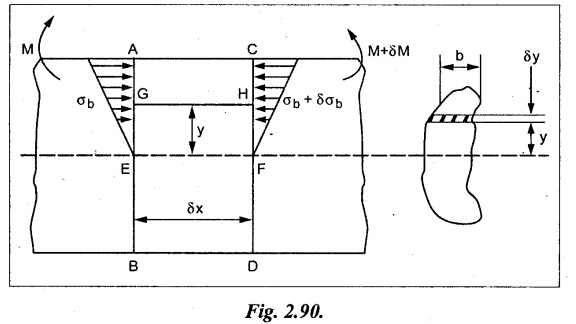
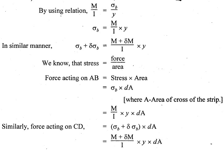
Consider a beam of uniform section subjected to bending moment M at the section AB and a bending moment M + δM at the section CD, and these two sections are kept dx distance apart as shown in Fig.2.90. Let σb be the stress at G due to M on a small area of width b and thickness dỵ. σb + δσb be the stress at H on a corresponding area of cross section CD.
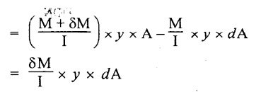
The net unbalanced force on the strip
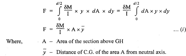
The total unbalanced force above the neutral layer may be found by integrating the above equation between 0 to d/2
To avoid the failure of the beam the unbalanced force developed above, the beam must offer shear resistance. This shear resistance at least must be equal to total unbalanced force to avoid failure due to shear.
Shear resistance = Total unbalanced force
Let,
q - intensity of horizontal shear at the level EF
b - width of the beam
Area on which the shear force is acting = b × dx
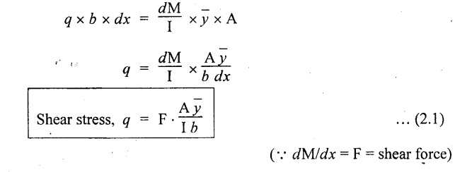
Shear force due to q = Shear stress × shear area
= q × b × dx ……(ii)
Equating the equation (i) and (ii)
The above shear stress is the horizontal shear stress at the distance y from the neutral axis. But the complementary shear stress (i.e., vertical shear stress) is accompanied by the horizontal shear of the same quality.
2. SHEAR STRESS DISTRIBUTION
In this section we shall study the distribution of the shear stress along the depth of a beam. We have to calculate the intensity of shear stress at important sections of a beam and sketch a shear stress distribution diagram. The following are the important section in practical cases over which the shear stresses distribution to be obtained.
1. Rectangular section.
2. Circular section
3. I-section
4. T-section
5. Triangular section
3. SHEAR STRESS DISTRIBUTION OVER A RECTANGULAR SECTION
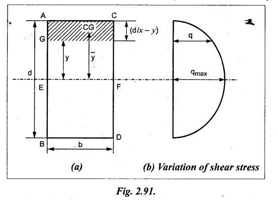
Consider a rectangular beam of which b and depth d as shown in Fig.2.91(a),
We know that the shear stress at a distance y from neutral layer,
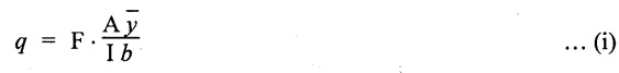
where, A – Area of the section above y
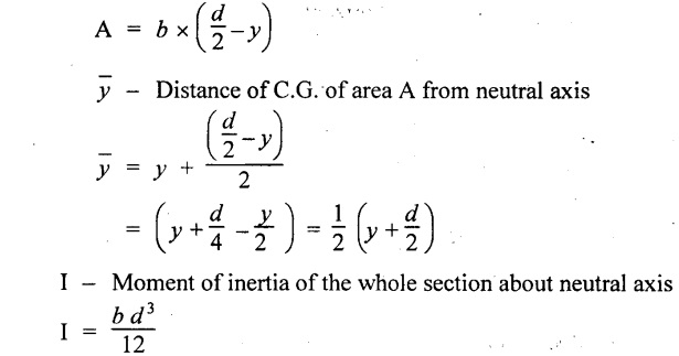
Substituting these values in the shear stress equation (i)
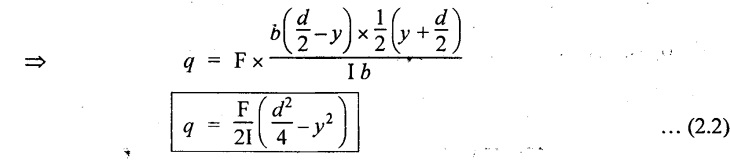
From the above equation, we see that q increases as y decreases. The above equation is an equation of a parabola.
At neutral axis when y = 0,
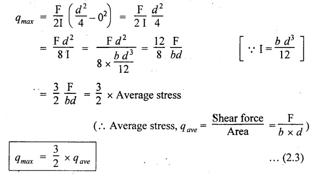
Therefore the maximum shear stress is 3/2 times the average shear stress.
At the top and bottom edge, when y = d/2
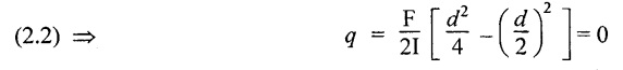
Therefore at the top and bottom edge, the shear stress is zero. The shear stress distribution is shown in Fig.2.91(b).
4. SHEAR STRESS DISTRIBUTION OVER A CIRCULAR SECTION
To determine the distribution of shear stress in a beam of circular cross section of radius R, consider a elementary strip at a distance y from neutral axis of width b and thickness 't' as shown in Fig.2.92.
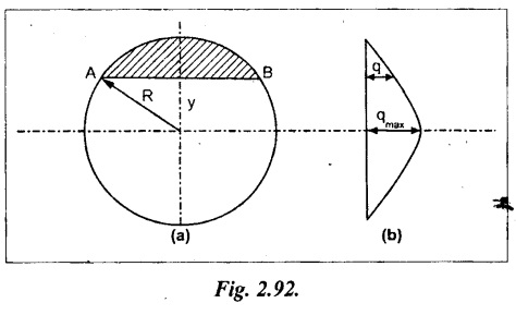
We know that the shear stress on a layer AB at a distance y from the neutral axis,
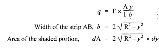
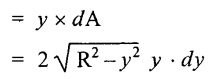
Moment of this area about the neutral axis,
= y × dA
Moment of whole shaded area about the neutral axis is obtained by integrating the above equation between limit y and R.
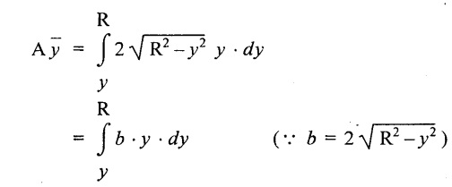
We know that width of the strip AB,
Differentiating both sides,
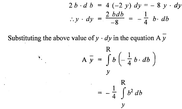
From the diagram when y = y, width b = b and when y = R, width b = 0.
Therefore the limits of integration may be changed from y & R to b and 0.
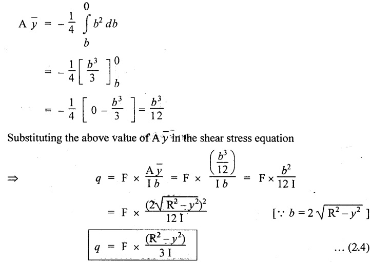
From the above equation, the shear stress distribution across a circular section is parabolic. Also we see that q increases a y decreases.
At y R, the shear stress q = 0. Hence shear stress will be maximum when y = 0.
At neutral axis, when y = 0,
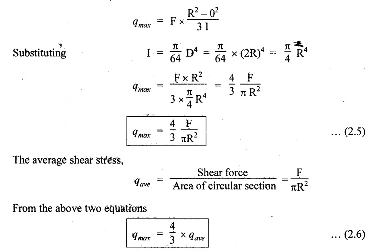
Therefore the maximum 'shear stress is 4/3 times the average shear stress. The shear stress distribution is shown in Fig.2.92(b).
5. SHEAR STRESS DISTRIBUTION OVER AN I-SECTION
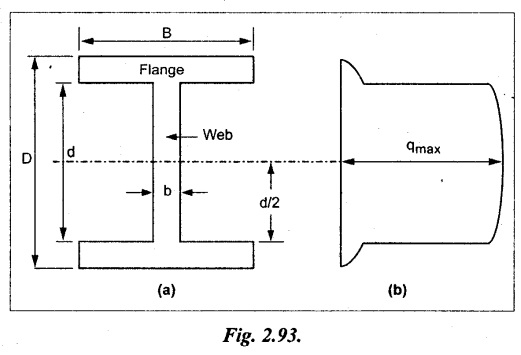
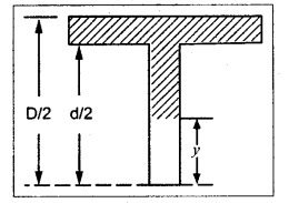
To determine the distribution of shear stress in the I-section, let B and D be the overall breadth and depth of the I-section, b and d be the breadth and depth of web section as shown in Fig.2.93(a).
The shear stress at a distance y from neutral axis is given by,
In the I-section the shear stress distribution in the web and shear stress distribution in the flange are to be calculated separately.
(a) Flange portion
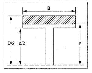
For flange portion,
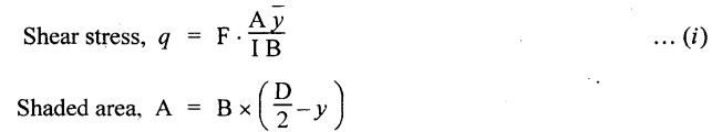
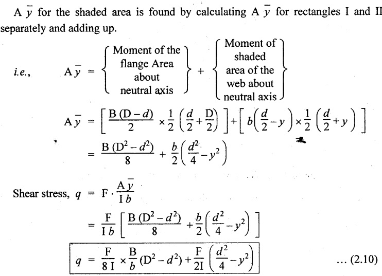
Distance of C.G. of the shaded area from Neutral axis,
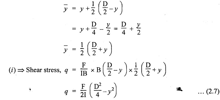
The variation of shear stress with respect to y in the flange is parabola.
And also shear stress decreases with increase of y.
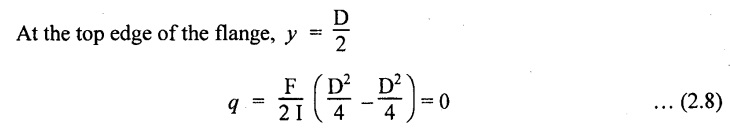
Hence at the top edge of the flange q is 0.
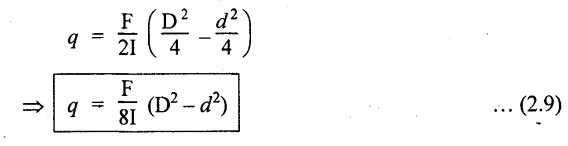
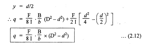
At the junction of the web and flange, y = d/2.
(b) Web portion:
Considering a portion of the web at a distance of y from neutral axis,
The above equation is an equation of parabola. Also with increase of y, q decreases.
At the neutral axis, y = 0 and hence shear stress is maximum.
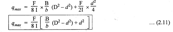
At the junction of the web and bottom of the flange,
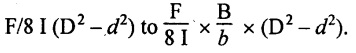
The shear stress distribution for the web and flange is shown in Fig.2.93(b). The shear stress at the junction of the flange and web changes abruptly. The equation F/8 I × (D2 - d2) gives the stress at the junction of the flange and the web when stress distribution is considered in the flange. But equation F/8 I × B / b × (D2 - d2) gives the stress at the junction when stress distribution is considered in web. By comparing the above equation it shows that the stress at the junction changes abruptly from
6. SHEAR STRESS DISTRIBUTION OVER T-SECTION
The procedure for determining the shear stress distribution for T-section is similar to that of I-section. But here the section is not symmetrical about x-x axis. Therefore first we have find out the ![]() by using the formula.
by using the formula.
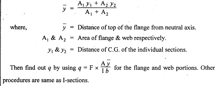
The shear stress distribution diagram is not symmetrical about x-x axis, since the section is not symmetrical about x-x axis.
7. SHEAR STRESS DISTRIBUTION OVER AN TRIANGULAR SECTION
Consider a triangular section ABC with b as base and h as height. For triangular sections the neutral axis lies at a distance of 2/3 h from the top as shown in Fig.2.94(a).
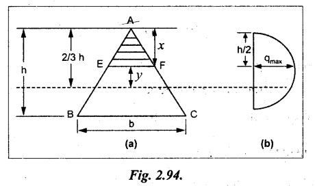
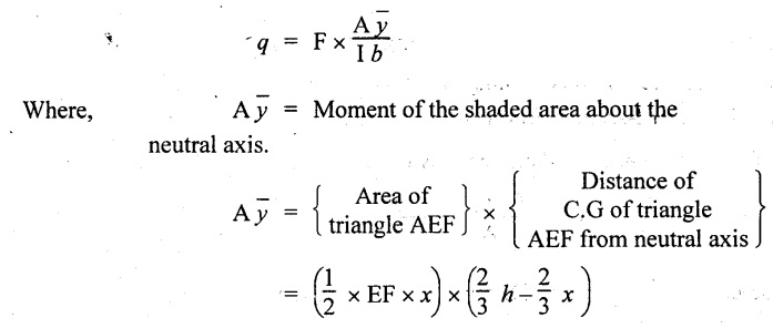
Consider an elemental strip EF at a distance of y from the neutral axis. The shear stress is given by
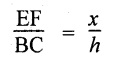
From similar triangles ABC and AEF
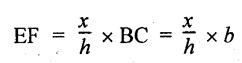
Width of the triangle AEF,
Substituting EF value in A ![]() equation
equation
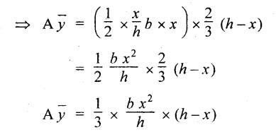
Substituting A ![]() value in the equation q,
value in the equation q,
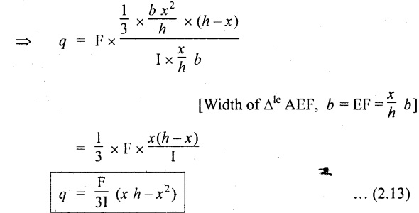
The above equation is an equation of parabola.
At the top, x = 0
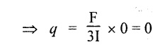
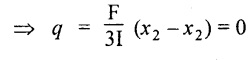
At the bottom, x = h
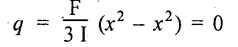
At the neutral axis, x = 2/3 h
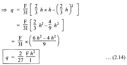
Maximum shear stress
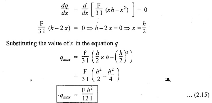
The maximum shear stress is obtained by differentiating the shear stress equation with respect to x and equating to zero.
The shear stress distribution diagram is as shown in Fig.2.94(b).
8. SOLVED PROBLEMS ON SHEAR STRESS DISTRIBUTION
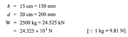
Example 2.74:
A rectangular beam of 15cm wide and 20 cm deep is subjected to load 2500 kg. Calculate the maximum shear stress. If load is distributed uniformly over the beam calculate maximum shear stress?
Given data:
To find:
(i) qmax
Solution:
(i) Point load is applied: Shear force applied on the beam
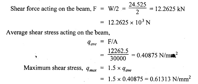
F = W = 24.525 kN = 24.525 × 10³ N
Cross section area of the beam, A = b × d = 150 × 200 = 30000 mm2
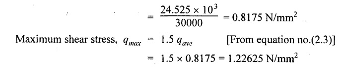
Average shear stress, qave = F/A
(ii) Uniformly distributed load is applied:
Result:
Maximum shear stress
(i) Point load is applied = 1.22625 N/mm2
(ii) Uniformly distributed load = 0.61313 N/mm2
Example 2.75:
A timber of rectangular section is to support a load 2 tons uniformly distributed over the span of 30 cm. If the depth of the section is to be twice the breadth and stress in timber not exceed 8 N/mm2. Find the dimensions of the cross section. How would you modify the cross section if it were a concentrated load placed at the center assuming the above ratio of breadth to depth?
Given data:
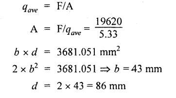
w = 2 tons = 2000 kg = 19620 N
l = 30 cm = 300 mm
d = 2b; qmax = 8 N/mm2
To find:
(i) b; (ii) d.
Solution:
(i) Apply uniformly distributed load:
Shear force applied on the beam
Average shear stress of the beam
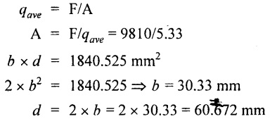
Cross section area of the beam
(ii) Point load applied at center of the beam
Shear force acting on the beam,
F = W = 19620 kN
Cross section area of the beam.
Result:
Cross section of the beam
(i) Uniformly distributed load = 30.33 × 60.67 mm
(ii) Point load at center = 43 × 86 mm
Example 2.76:
A timber of 35 mm depth and 50 mm height has a span of 200 mm. The maximum shear stress not exceed 10 N/mm2. Calculate the load carried by the beam as per the following conditions: (i) Point load at center (ii) Uniformly distributed load over a span?
Given data:
b = 35 mm;
d = 50 mm;
l = 200 mm;
qmax = 10 N/mm2
To find:
(i) W; (ii) w.
Solution:
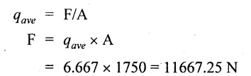
Average shear stress of the beam
qmax = 1.5 qave
qmax = 10/1.5 = 6.667 N/mm2
Cross section area of the beam
A = b × d
= 35 × 50 = 1750 mm2
Shear force acting on the beam
(i) Point load applied at the center:
W = F
⸫ 11667.25 N = 1189.32 kg
(ii) For uniformly distributed load:
W = 2 × F
= 2 × 11667.25
= 23334.5 N = 2378.65 kg
Result:
Load carried by the beam
(i) Point load at center = 1189.3 kg
(ii) Uniformly distributed load = 2378.65 kg
Example 2.77:
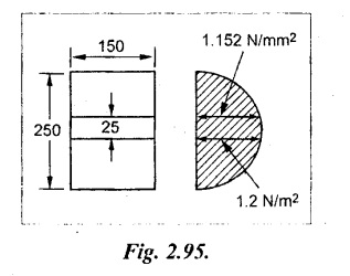
A rectangular beam 150 mm wide and 250 mm deep subjected to a maximum shear force of 30 kN.
Determine,
(i) Average shear stress
(ii) Maximum shear stress
(iii) Shear stress at a distance 25 mm above the neutral axis.
Given data:
b = 150 mm
d = 250 mm
F = 30 kN = 30 × 103 N
To find:
(i) qave; (ii) qmax; (iii) qat 25 mm
Solution:
Cross sectional area of the beam
A = b × d
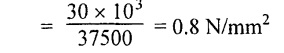
150 × 250 = 37500 mm2
Average shear stress, qave = F/A
Maximum Shear stress, qmax = 1.5 × qave
= 1.5 × 0.8 = 1.2 N/mm2
Shear stress at a distance 25 mm above neutral axis
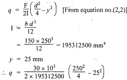
= 1.152 N/mm2
Result:
Average shear stress = 0.8 N/mm2
Maximum shear stress = 1.2 N/mm2
Shear stress at 25 mm above neutral axis= 1.152 N/mm2
Example 2.78:
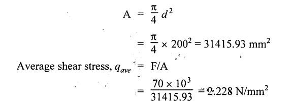
A circular beam of 200 mm diameter and the beam subjected to shear force of 70 kN. Calculate maximum and average shear stress?
Given data:
d = 200 mm; F = 70 kN = 70 × 103 N
To find: (i) qmax; (ii) qave.
Solution:
Cross section area of circular beam,
We know that,
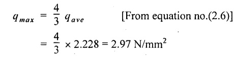
Maximum shear stress for circular beam
Result:
Average shear stress = 2.228 N/mm2
Maximum shear stress = 2.97 N/mm2
Example 2.79:
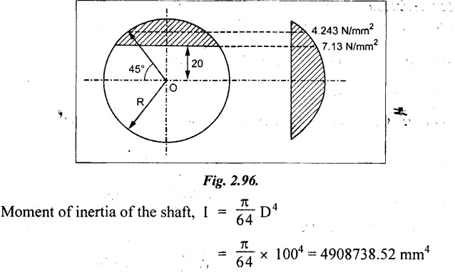
A circular beam of 100 mm diameter subjected to shear force of 50 kN. Calculate the shear stress as per the following conditions.
(i) 20 mm above from the neutral axis
(ii) 45° from horizontal neutral axis.
Given data:
D = 100 mm; R = 50 mm;
F = 50 kN = 50 × 103 N;
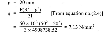
y = 20 mm
θ = 45°
To find:
(i) q
Solution:
Shear stress of the beam 20 mm above neutral axis
Shear stress of the beam at angle of 45°
⸫ y = R sin θ
= 50 × sin 45° = 35.36 mm
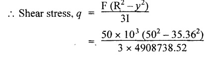
= 4.243 N/mm2
Result:
Shear stress of circular shaft
(i) 20 mm above neutral axis = 7.13 N/mm2
(ii) At 45° from neutral axis = 4.243 N/mm2
Example 2.80:
A beam of triangular cross section having base width of 150 mm and height of 250 mm is subjected to a shear force of 10 kN. Find the value of maximum shear stress, and shear stress in neutral axis?
Given data:
b = 150 mm
h = 250 mm
F = 10 kN = 10 × 103 N
To find:
(i) qmax; (ii) qna
Solution:
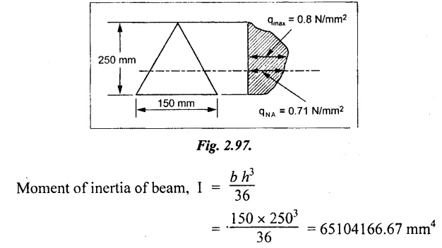
Maximum shear stress of beam,
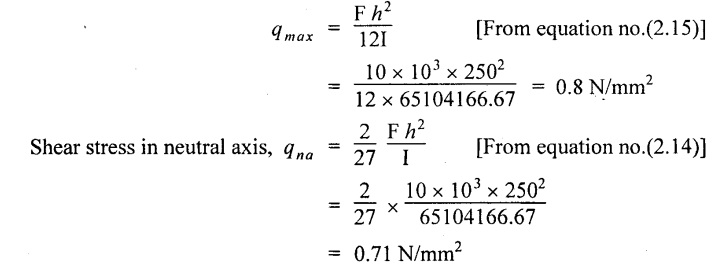
Result:
Maximum shear stress of beam = 0.8 N/mm2
Shear stress in neutral axis = 0.71 N/mm2
Example 2.81:
A 400 mm × 150 mm I girder has 20 mm thick flanges and 30 mm thick web. Calculate maximum intensity of shear stress when the shear force at the cross section is 1.6 MN. Also sketch the shear stress distribution across the depth of beam?
Given data:
D = 400 mm
B = 150 mm
t = 20 mm
b = 30 mm
F = 1.6 MN = 1.6 × 10⁶ N
To find:
(i) qmax
Solution:
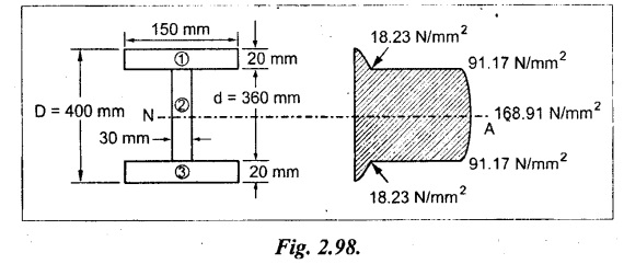
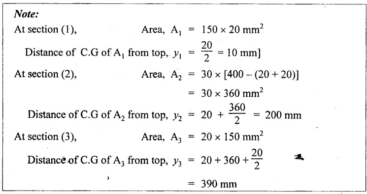
Center of gravity of the section from top face
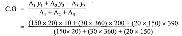
= 200 mm
Moment of inertia of the beam,
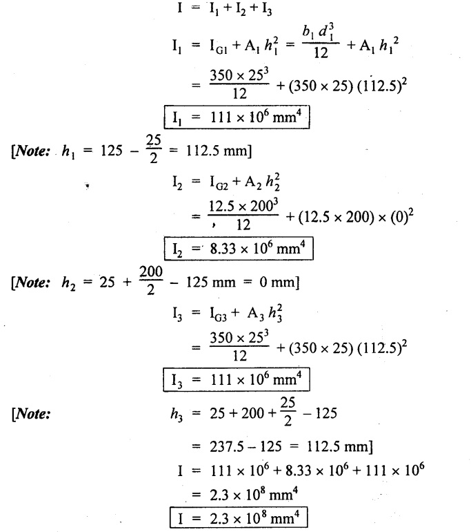
I = I1 + I2 + I3
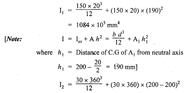
= 1166.4 × 105 mm4
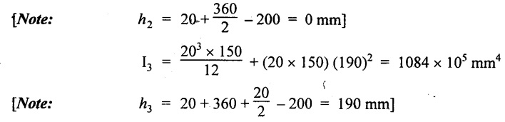
⸫ Moment of inertia of the beam
I = (1084 + 1166.4 + 1084) × 105
= 3334.4 × 105 mm4
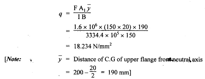
Shear stress in the upper flange with web,
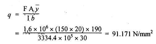
Shear stress in the web with upper flange,
Maximum shear stress of the beam
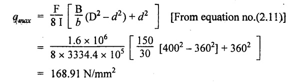
Result:
Maximum-shear of beam = 168.91 N/mm2
Example 2.82:
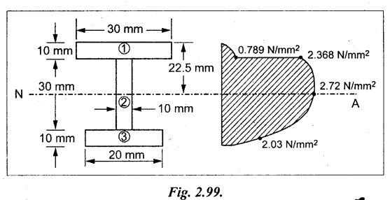
A cast iron bracket of I-shape with unequal flanges as shown in figure. If the section is subjected to a shear force of 1 kN. Draw the shear stress distribution over the depth of the section.
Given data:
F = 1 kN = 1 × 10³ N
To find:
(i) qmax
Solution:
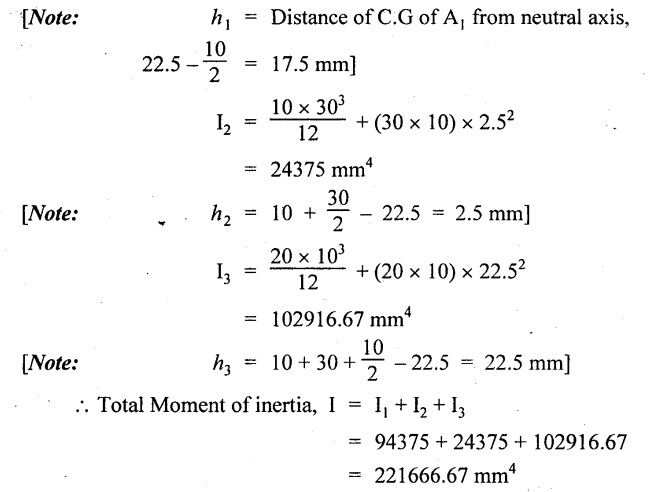
Moment of inertia of the beam
I = I1 + I2 + I3
I1 = Ixx + A h2
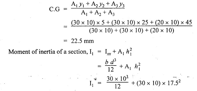
Center of gravity of the beam from top face
= 94375 mm4
Shear stress in the upper flange at the junction with web,
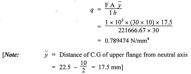
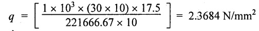
Shear stress in the web at the junction of upper flange,
Shear stress in the neutral axis, q = 1 × 103
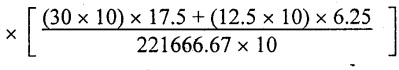
= 2.721 N/mm2
Shear stress in the lower flange at the junction with web,
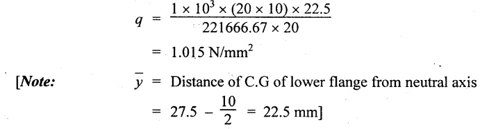
Shear stress in the web at the junction with lower flange,
Result:
Maximum shear stress of beam = 2.721 N/mm2
Example 2.83:
A beam supported at its ends has a span of 2m and carries a uniformly distributed load of 200 kN/m over the entire span. The cross section of the beam is shown in figure. Calculate the maximum shear stress in the beam. Also draw the shear stress distribution marking principle values.
Given data:
w = 200 kN/m; l =2m = 2000 mm
To find:
(i) qmax
Solution:
Shear force on the beam:
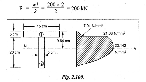
Center of gravity of the beam from top face
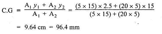
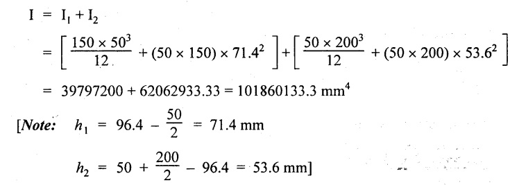
Moment of inertia of the beam,
Shear stress in flange at the junction with web,
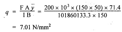
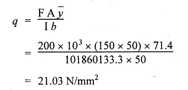
Shear stress in the web at the junction with flange,
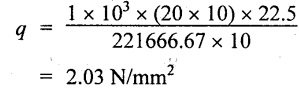
Maximum shear stress of the beam
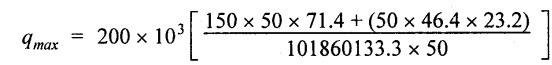
= 23.142 N/mm2
Result:
Maximum shear stress = 23.142 N/mm2
Example 2.84:
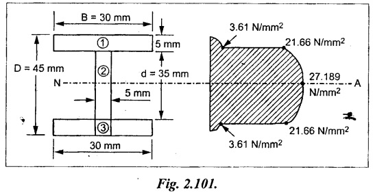
A I section as shown in sketch spans two supports 5 m apart. A 10 kN load is distributed uniformly on the entire span of beam. Calculate maximum shear stress and draw the shear distribution diagram?
Given data:
w = 10 kN = 10 × 103 N
D = 45 mm
B = 30 mm
b = 5 mm
d = 35 mm
To find:
(i) qmax
Solution:
Shear force applied on the beam
Moment of inertia of the beam
Refer problem no.2.82.
I = 1.385 × 105 mm4
Maximum shear force applied
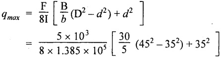
= 27.189 N/mm2
Shear stress in flange at the junction with web,
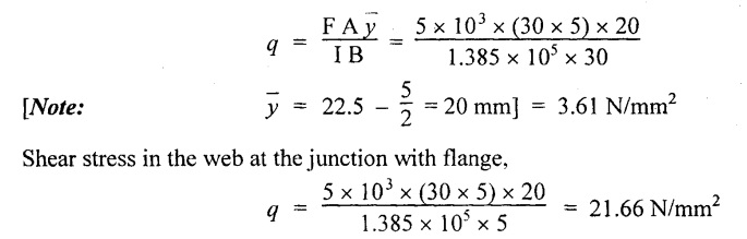
Result:
Maximum shear stress on the beam = 27.189 N/mm2
9. UNIVERSITY SOLVED PROBLEMS ON SHEAR STRESS DISTRIBUTION
Example 2.85:
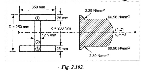
A I section beam 350 mm × 200 mm has a web thickness of 12.5 mm and a flange thickness of 25 mm. It carries a shearing force of 20 tonnes at a section. Sketch the shear stress distribution across the section.
Given data:
F = 20 tonnes
= 20 × 1000 × 9.81 = 1.962 × 10⁵ N
To find:
Sketch the shear stress distribution
Solution:
Centre of gravity of the section from top face
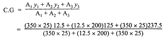
C.G = 125 mm
Otherwise, for section symmetric about x-x axis the C.G lies at the distance of depth/2.
i.e., 250 / 2 = 125 mm
Moment of inertia of the beam,
Shear stress in the upper flange with web
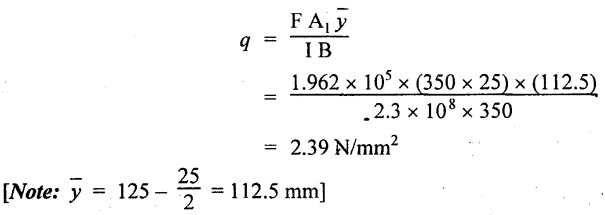 Shear stress in the web with upper flange
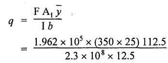
= 67.17 N/mm2
The maximum shear stress lies in neutral axis, since beam is symmetric about X-X axis. Therefore, maximum shear stress of the beam,
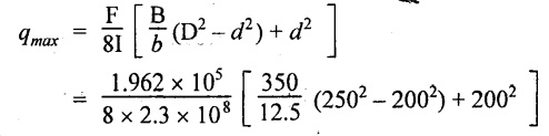
= 71.21 N/mm2
Result:
The shear stress distribution across the section is shown in Fig.2.102.
Example 2.86:
A beam of I section 50 cm deep and 19 cm wide has flange 2.5 cm thick and web 15 cm thick. It carries a shearing force of 40 tonnes at a section. Calculate the maximum intensity of shear stress in the section. Assuming the moment of inertia to be 64,500 cm4. Sketch the shear stress distribution across the section.
[Same as previous university solved problem].
Example 2.87:
A cross section of a beam in the form of a triangle with base = 200 mm and depth 300 m. If the shear force on the beam is 60 kN, study the distribution determine the maximum shear stress.
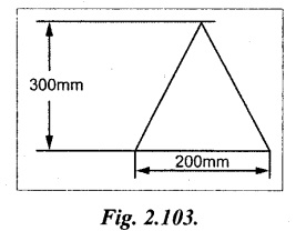
Given data:
Shear force, F = 60 kN = 60 × 103 N
To find:
Study the distribution
Solution:
Maximum shear stress:
The general shear stress equation for triangle is given by
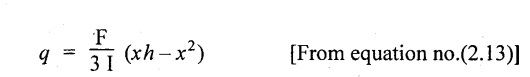
The above equation is an equation of parabola.
At the vertex portion, x = 0
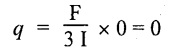
At the bottom of the triangle, x = h
At the neutral axis which is passing at a distance of 2/3 h from bottom or 1/3 h from vertex
i.e.,
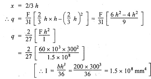
q = 2.667 N/mm2
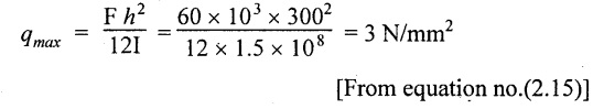
The maximum shear stress is given by
Result:
At the neutral axis, q = 2.667 N/mm2
At vertex and bottom portion, q = 0
The maximum shear stress, qmax = 3 N/mm2.
Example 2.88:
A I-shaped cross section of a beam 200 × 50 mm flanges, 200 × 50 mm web is subjected to a vertical shear force of 100 kN. Calculate the shear stress at the neutral axis and at the junction of the web and the flange.
[Same as university solved problem 2.85].
Example 2.89:
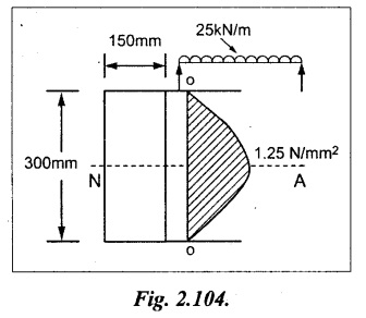
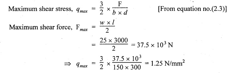
A wooden beam 150 mm wide and 300 mm deep and 3 m long is carrying UDL of 25 kN/m over the entire length. The beam is simply supported at the ends. Determine the maximum shear stress and sketch the shear stress variation along depth of the beam.
Given data:
Width, b = 150 mm
Depth, d = 300 mm
Length, l = 3 m = 3000 mm
UDL, w = 25 kN/m = 25 N/mm
To find:
(i) Maximum shear stress.
(ii) Draw shear stress variation along the depth.
Solution:
The shear stress is zero at top and bottom most layer and maximum at neutral axis and it varies parabolically along the depth of the beam.
Result:
The maximum shear stress, qmax = 1.25 N/mm2.
Shear stress distribution diagram is shown in Fig.2.104.
Example 2.90:
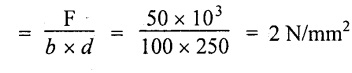
A rectangular beam 100 mm wide and 30 mm deep is subjected to a maximum shear force 50 kN. Determine (i) Average shear stress (ii) Maximum shear stress and (iii) Shear stress at a distance of 25 mm above the neutral axis.
Given data:
Width, b = 100 mm
Depth, d = 250 mm
Shear force, F = 50 kN = 50 × 103 N
To find:
(i) Average shear (qave)
(ii) Maximum shear stress (qmax)
(iii) Shear stress at a distance of 25 mm above the neutral axis.
Solution:
(i) Average shear stress (qave)
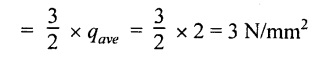
(ii) Maximum shear stress (qmax)
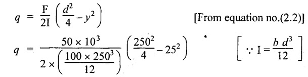
(iii) Shear stress at a distance of 25 mm above the N.A.
= 2.88 N/mm2
Result:
(i) Average shear stress, qave = 2 N/mm2
(ii) Maximum shear stress, qmax = 3 N/mm2
(iii) Shear stress at a distance of 25 mm above the N.A. = 2.88 N/mm2
Example 2.91:
A beam is subjected to a shear force of 20 kN. The cross section of the beam is of rectangular section 8 cm breadth and 12 cm depth. Draw shear stress distribution across the depth of every 2 cm.
Given data:
Shear force, F = 20 kN = 20 × 103 N
Breadth, b = 8 cm = 80 mm
Depth, d = 12 cm = 120 mm
To find:
Draw the shear stress distribution across the depth of every 20 mm.
Solution:
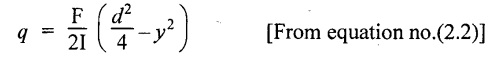
Shear stress at any section of the rectangular beam is given by
(i) Shear stress at 20 mm from bottom layer is
y = Distance from NA to where we have to find shear stress
y = 60-20 = 40 mm
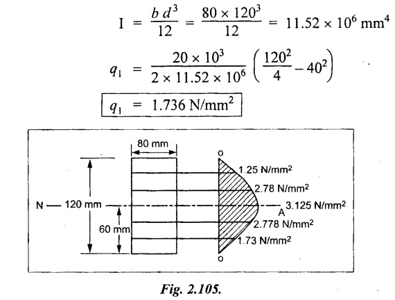
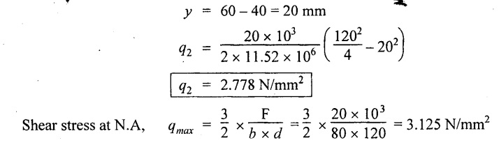
(ii) Shear stress at 40 mm from bottom layer,
The section is symmetric about X-X axis. Therefore the shear stress is also symmetric in manner
Shear stress at a distance of 80 mm from bottom surface
q4 = q2 = 2.778 N/mm2
Shear stress at a distance of 100 mm from bottom surface
q5 = q1 = 1.736 N/mm2
The shear stress is zero at top and bottom surface.
Result:
The Shear stress distribution across the depth of every 20 mm is shown in Fig.2.105.
No comments:
Post a Comment