If a beam is bend only due to application of constant bending moment and not due to shear, then it is called simple bending or pure bending.
THEORY OF SIMPLE BENDING
1. INTRODUCTION
The following are the main objectives of the theory of simple bending. To determine,
(i) The stresses developed to resist the bending moment (i.e., Bending stress)
(ii) The stresses developed to resist the shear force (i.e., Shearress)
If a beam is bend only due to application of constant bending moment and not due to shear, then it is called simple bending or pure bending.
2. ASSUMPTIONS IN SIMPLE BENDING
The following are the assumptions in theory of simple bending.
(i) The material is perfectly homogeneous and isotropic. It obeys Hooke's law.
(ii) The value of young's modulus is same in tension as well as in compression.
(iii) Transverse sections, which are plane before bending, remains plane after bending.
(iv) The radius of curvature of the beam is very large compared to the cross sectional dimension of the beam.
(v) Each layer of the beam is free to expand or contract, independently of the layer, above or below it.
(vi) The resultant force on a transverse section of the beam is zero.
3. DERIVATION OF BENDING EQUATION
Let us consider a beam acted upon by two equal moments (M) at the ends as shown in Fig.2.63.
 The BM induced by the moment tends to bend the beam in a concave manner. So, the top surfaces (AC) are subjected to compressive stresses and contract while the bottom surfaces (BD) are subjected to tensile stresses and extend. However, there is a layer EF in between the top and bottom, which will retain its original length even after bending (E'F'). This layer EF which is neither compressed or stretched is known as the neutral layer or neutral plane. In Fig, OH represents a typical layer of material at a distance 'y' from neutral plane. R is the radius of curvature of the portion of the neutral layer in the bend beam.
The following steps are involved in the development of bending theory.
(a) Determination of strain in layer G'H'
(b) Evaluation of stress in this layer by means of Young's modulus.
(c) Determination of load carried by the strip of cross section at a distance y from neutral plane.
(d) Calculating the moment produced by this load about neutral plane, and summation of the total moment of all such strip loads.
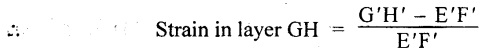
Step (a): Determination of strain in layer G'H'
Change in length of layer GH after bending = G'H' – GH

But, GH = EF and EF = E'F' (because of neutral plane)
Expressing the above equation in terms of R and θ,
The arc length G'H' = (R+ Y) θ
The arc length E'F' = R θ

Step (b): Stress (σb) in layer G'H'
We know that young's modulus,

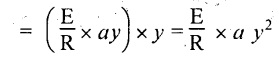
Step (c): Load carried by G'H'
Let a - Area of cross section of strip at G'H'
We know that,

Step (d): Moment of layer at G'H'
Moment (M) of the load on this strip about neutral layer
M = Load × Distance
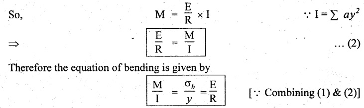
The total moment of the beam section made up of all such moments

But, ⅀ ay2 is the second moment of area and it has been defined as moment of inertia,
Note
1. Maximum stress takes place at the outer most layer.
2. Stress at a point is directly proportional to its distance from the neutral axis.
3. In a symmetrical section the centre of gravity lies at the geometrical center of the section. For that sections the 'y' lies at a distance of d/2 or h/2, from its outermost layer. Where d is a diameter for circular section and h is a depth for square or rectangular section.
4. SECTION MODULUS OR MODULUS OF SECTION
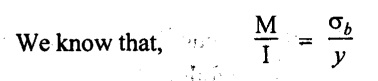
We know the equation of the beam is

Instead of dealing two quantities I and y, we can use a single property in l/y. This ratio is a measure of the property of the section to resist bending known as 'Section modulus' or 'modulus of section' denoted by Z.
Otherwise, it is the ratio of moment of inertia about the neutral layer to the distance of the extreme layer from the neutral axis (NA).
Therefore, M = σb . Z
Where,
M = Moment of resistance.
The values of I, Z for rectangular, hollow, circular and I section are shown in Table 2.1.
 5. FLITCHED BEAMS OR COMPOSITE BEAMS
Sometimes, the section of a beam may be constructed by two different materials. This is mainly used to strengthen the material. E.g. Presence of steel strips in wooden beams or steel bars in concrete beams. These beams are called flitched beams or composite beams.
If both the material have been rigidly joined together, they will behave like a unit piece and the bending will take place about the combined axis. The total moment of resistance will be equal to the sum of moment of resistance of individual sections.
Consider a flitched beam consists of steel strips on wooden beam and denoted by 1 and 2 respectively.

As the two are rigidly connected together, the strains in the both at the various surface will be equal. Therefore at any common surface,
 Total moment of resistance of the composite section,
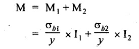
Substituting σb2 value in the above equation
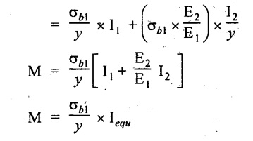
Where, 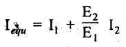 is called the equivalent moment of inertia of the composite section. If m = E2/E1, is the modular ratio,
⇒ Iequ = I1 + m I2
6. SOLVED PROBLEMS ON THEORY OF SIMPLE BENDING
Example 2.50:
A simply supported beam which is having rectangular section of 60 × 35 mm and 3m long carrying a load of 5 kN at mid-span. Determine the maximum bending stress induced in the beam.
Given:
Simply supported beam,
Breadth, b = 60 mm
Height, h = 35 mm
Length, l = 3 m
Load, W = 5 kN
To find:
Maximum bending stress, σb.
Solution:
Bending moment, M at centre:
Taking moment about A,
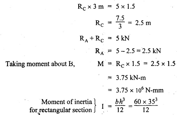
= 214375 mm4
Maximum bending stress will occur at centre of the height of the beam
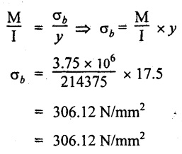
From the theory of simple bending equation
Result:
Maximum bending stress, σbmax = 306.12 N/mm2
Example 2.51:
A aluminium plate of 150 mm width and 25 mm thickness is bend into a circular arc of radius 8 m. Determine the maximum bending stress and the moment produced by the maximum bending stress. Take E = 1 × 10⁵ N/mm2.

Given:
Width, b = 150 mm
Thickness, t = 25 mm
Radius of curvature, R = 8 m = 8000 mm
Young's modulus, E = 1 × 10⁵ N/mm2
To find:
σbmax, Mmax
Solution:

Maximum bending stress occurs at mid thickness of the plate,

= 2.44 × 10⁶ N-mm
= 2.44 kN-m
Result:
Maximum bending stress, σbmax = 156.25 N/mm2
Maximum bending moment, Mmax = 2.44 kN-m
Example 2.52:
The cross section of the beam is shown in Fig. 2.67. This beam is of cantilever type and carries a UDL of 16 kN/m. If the span of the beam is 2.5 m, determine the maximum tensile and compressive stresses in the beam.

Given:
UDL = 16 kN/m
L = 2.5 m
Area of section (1), a1 = 50 × 10 = 500 mm2
Area of section (2), a2 = 15 × 35 = 525 mm2
y1 for section (1) from bottom most layer
y2 for section (2) from bottom most layer

For unsymmetrical section, the centre of gravity of the section is placed ‘y' mm from the bottom face. They may be calculated by using the following formula.

Moment of inertia of rectangle (1) about an axis through its C.G. and parallel to X-X axis,

From parallel axis theorem moment of inertia of the rectangle (1) from X-X axis,

Similarly for section (2)
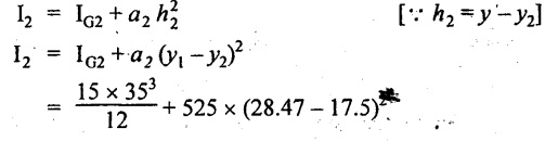
= 53593.75 + 63178.97
= 116772.72 mm4
Now moment of inertia of whole section about x axis,
Ixx = I1 + I2
= 70637.11 + 116772.72
= 187409.83 mm4
Moment, M = 16 kN/m × 2.5 × 2.5/2 = 50 kN-m
The maximum compressive bending stress is on the top most layer of the beam.
⸫ The distance from y to top layer is
= 45 - 28.47 = 16.53 mm
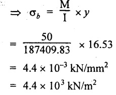
= 4.4 × 10⁻³ kN/mm2
= 4.4 × 10³ kN/m2
The maximum tensile stress is on the bottom most layer of the beam.

Result:
The Maximum tensile stress = 7.59 × 10³ kN/m2
The Maximum compressive stress = 4.4 × 10³ kN/m2
Example 2.53:
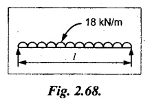
A beam of symmetrical cross section has a depth of 40 mm and a moment of inertia 362540 mm4 about its axis of bending. Find the maximum permissible span for this beam if, simply supported at the ends, it has to carry to UDL of 18 kN/m run without exceeding a bending stress of 8 × 10⁻³ kN/mm2.
Given:
Depth, d = 40 mm
Moment of inertia, I = 362540 mm4
UDL = 18 kN/m = 18 N/mm
σb = 8 × 10⁻³ kN/mm2 = 8 N/mm2
Simply supported at its end.
To find:
Length of the beam
Solution:
For simply supported beam, BM at the centre for the given structure as shown in Fig.2.68 is

Result:
Length of the beam, l = 253.87 mm
Example 2.54:
A beam of symmetrical section is 300 mm deep and has a moment of inertia of 7 × 107 mm4 about its principle axis. To what radius may it be bend if the maximum stress is not to exceed 80 N/mm2? Take E = 2 × 10⁵ N/mm2. What would be the moment of resistance at this stress?
Given:
Depth, d = 300 mm
MOI, I = 7 × 104 mm4
σb max = 80 N/mm2
E = 2 × 10⁵ N/mm2
To find:
(i) Radius of curvature, R
(ii) Moment of resistance
Solution:
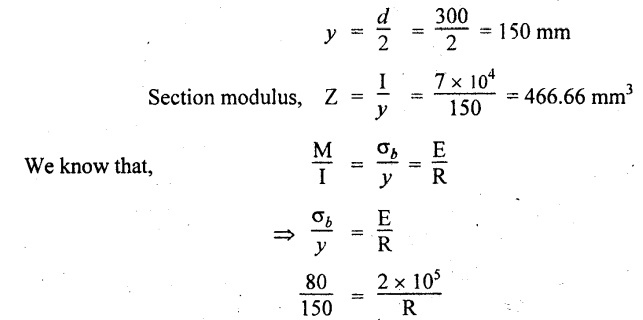
R = 375000 mm = 375 m
Moment of resistance, M = σb • Z
= 80 × 466.66
= 37332.8 N-mm = 37.33 Nm
Result:
(i) Radius of curvature, R = 375 m
(ii) Moment of resistance, M = 37.33 Nm
Example 2.55:
An I section as shown in sketch spans two supports 1.5 m apart. Determine the total load uniformly distributed on the entire span that the beam could carry in addition to a concentrated load of 8 kN at its centre in order that extreme fibre stress is limited to 800 N/mm2.
Given:
L = 1.5 m = 1500 mm
W = 8 kN
σb = 800 N/mm2
Solution:
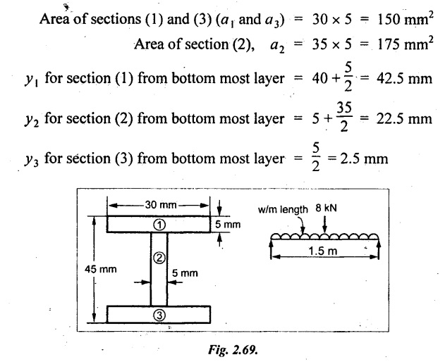
The section is symmetrical about X-X axis, therefore the C.G will lie on the axis.

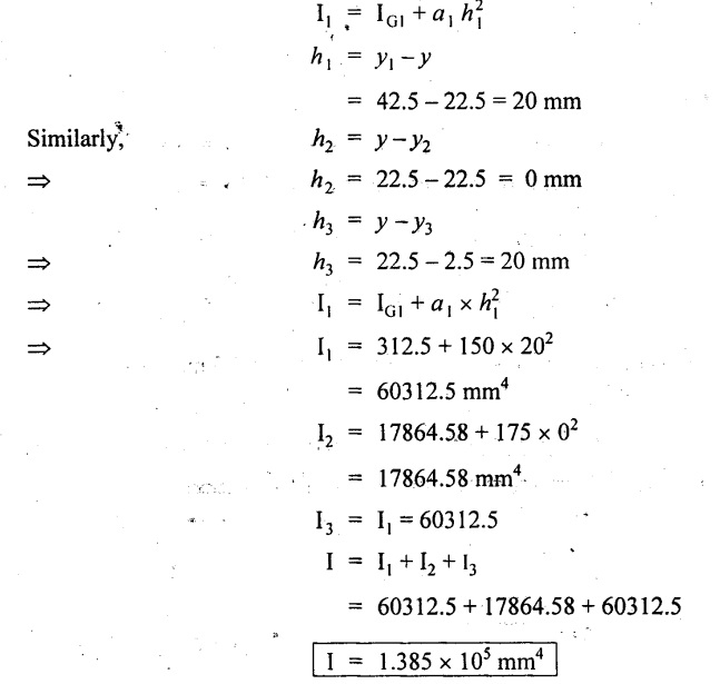
MOI of rectangles about an axis through its centre.

From parallel axis theorem,
The maximum bending moment, the beam can withstand,
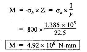
Maximum BM due to the concentrated load of 8 kN at the centre
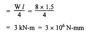
So, BM permissible due to uniformly distributed load
= Max moment - Moment due to point load
= 4.92 × 10⁶ - 3 × 106
= 1.92 × 10⁶ N-mm
If 'w' is the total UDL,
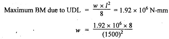
w = 6.83 N
Result:
Total UDL that the beam can carry is 6.83 N.
Example 2.56:
A model beam of 50 mm diameter is broken by a transverse load of 900 N applied at the center of the span 0.8m. Using the factor of safety of 3, calculate the safe load for a beam of 110 mm diameter, freely supported over a span of 2 m.
Given:
For model beam, d1 = 50 mm,
W1 = 900 N, l1 = 0.8m
For actual beam, d2 = 110 mm, l2 = 2m
Factor of safety = 3
To find:
W2
Solution:
For model beam:

The maximum BM that the model beam can carry,
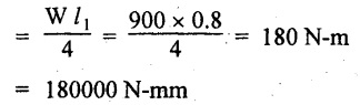
For circular cross section, moment of inertia,

For actual beam:
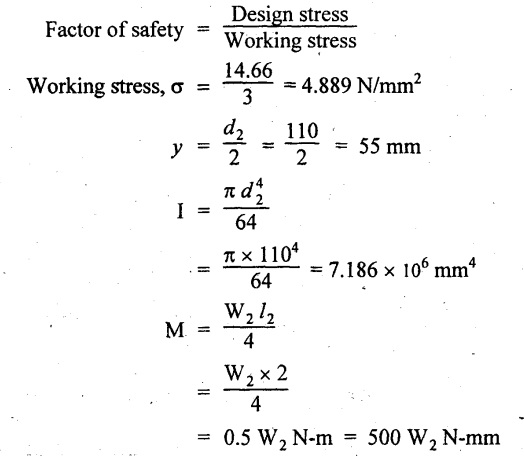
Using the relation,
W2 = 1277.69 N
= 1.277 kN
Result:
The safe load for actual beam = 1.277 kN
Example 2.57:
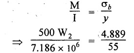
A simply supported beam of 6m span is subjected to two point loads of each 60 kN at one third span. The permissible bending stress for the beam material is 120 N/mm2. Design the beam as a rectangular section keeping breadth as half of depth. Neglect self weight of the beam.
Given:
W1 = W2 = 60 kN
To find:
b and d of the beam

Solution:
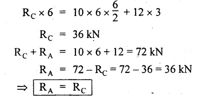
Taking moment about A,
RB × 6 = 60 × 4 + 60 × 2

RA + RB = 60 + 60 = 120 kN
⇒ RA = 120 kN - 60 kN
= 60 kN
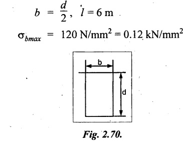
The loading is symmetrical about X-X and Y-Y axis. Therefore, maximum BM is at the centre of the beam,
The BM at centre = RB × 3 - 60 × 1
By using relation,

Result:
Breadth, b = 114.47 mm
Depth, d = 228.94 mm
Example 2.58:
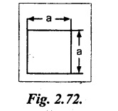
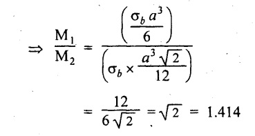
A beam of square section of side is 'a'. If the permissible stress is 'f' find the moment of resistance when the beam section is placed such that (i) two sides are horizontal (ii) one diagonal is vertical. Find also the ratio of the moments of resistance of the section in the two positions.
Given:
Side = a,
Stress = σb
To find:
(i) Moment of resistance
(ii) Ratio of moment od resistance
Solution:

Ratio of moment of resistance of the section in two position,
Result:
Moment of resistance, when

Example 2.59:
Find the dimensions of a timber joist span 5 m to carry a brick wall 200 mm thick and 3.2 m high, if the weight of brickwork is 19 kN/m3 and the maximum stress is limited to 8 N/mm2. The depth is to be twice the width.
Given:
l = 5 m
Dimensions of brick wall:
Thickness, t = 200 mm = 0.2 m
Height, h = 3.2 m
Density, ρ = 19 kN/m3
σb max = 8 N/mm2
d = 2b
To find:
Dimensions of timber joist (i.e., b and d)
Solution:
Weight of the brick wall, W = ρ × t × h × l
= 19 × 0.2 × 3.2 × 5
W = 60.8 kN
The brick wall is spread over entire length of the timber joist therefore it is considered as UDL.
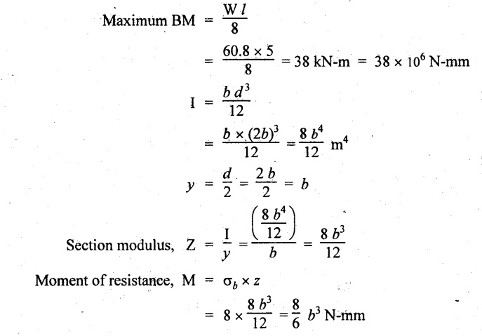
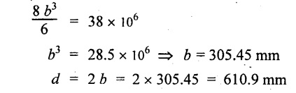
Equating the moment of resistance to maximum BM,
Result:
Dimension of the timber joist,
Breadth, b = 305.45 mm
Depth, d = 610.9 mm
Example 2.60:
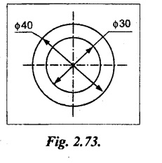
A mild steel tube 40 mm outside diameter and 30 mm inside diameter is used as a simply supported beam on a span of 1.8 m and it is found that the maximum safe load it can carry at mid span is 1200 N.
Four of these tubes are placed parallel to one another and firmly fixed together to form in effect a single beam, the centers of the tubes forming a square of 40 mm side with one pair of centers vertically over the other pair. Find the maximum central load which this beam can carry if the maximum stress is not to exceed that of the single tube above.
Given:
D = 40 mm;
d = 30 mm
W = 1200 N;
L = 1.8 m
Case (a): Single tube
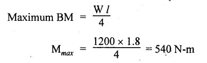
= 540 × 103 N-mm
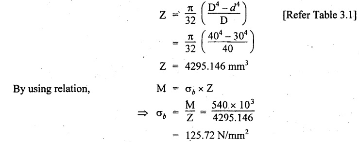
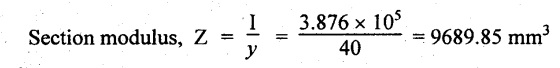
Section modulus of single tube,
Case (b): Composite tube
Moment of inertia of the composite beam about neutral axis is the sum of the MOI of individual tube about that axis.
MOI of the single tube about neutral axis is,
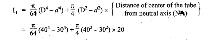
= 85902.92 + 10995.57 = 96898.49 mm4
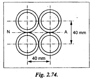
For total section
I = 4 × I1 = 4 × 96898.49 = 3.876 × 105 mm4
(⸪ Four sections are similar)
If W1 is the concentrated load,

W1 = 2707.128 N
Result:
Maximum central point load, W1 = 2707.128 N
Example 2.61:
A 250 mm × 120 mm rolled steel joist is used as a cantilever of 3 m length. If the permissible stress in bending is 95 N/mm2, what is the UDL that can be carried by it?
If the cantilever is to be strengthened by steel plates 15 mm thick welded to the top and bottom flanges, find out the width of the plates required to withstand an increase of 70% in the load. The length over the plates and the maximum bending stress remains the same.
Properties of I section are
(i) Area = 145.6 × 106 mm4
(ii) Thickness of web = Thickness of flange
Given:
Length, l = 3 m
σbmax = 95 N/mm2
Thickness of the welded plate = 15 mm
Increase in load = 70%
MOI of section without plates, I1 = 145.6 × 106 mm4

To find:
(i) UDL
(ii) Width of the welded plate
Solution:
Let 'w' be the UDL
Maximum BM at fixed end for cantilever beam,

Let b be the width of the 15 mm thick plate welded at top and bottom.

I = 145.6 × 10⁶ + 5.2668 × 10⁵ b
The load is increased by 70%.

Equating both the I,
145.6 × 10⁶ + 5.266 × 10⁵ b = 2.77 × 10⁸
b = 249.48 mm
Result:
(i) UDL = 24.59 N/mm
(ii) Width of the plates required, b = 249.48 mm
Example 2.62:
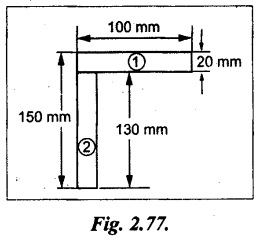
A 150 × 100 × 20 mm unequal angle bar is placed with the longer leg vertical and used as a joist freely supported at the ends. Find what UDL will be carried by the joist over a span of 4m if the maximum bending stress is not to exceed 5 MN/m2 and assuming that the section bends about the X-X axis.
Given:
L = 4 m;
σbmax = 5 MN/m2 = 5 N/mm2
To find:
UDL
Solution:
Area of section (1), a1 = 100 × 20 = 2000 mm2
Area of section (2), a2 = 130 × 20 = 2600 mm2
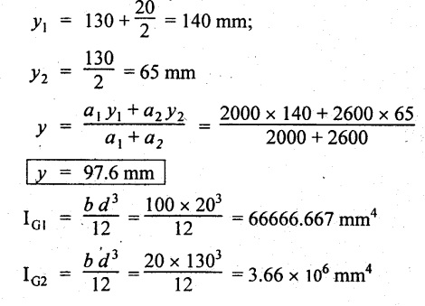
From parallel axis theorem,
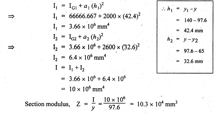
The moment of resistance,
M = σb × Z = 5 × 10.3 × 104
= 5.16 × 10⁵ N-mm
If 'w' is the total UDL over the span,

Equating the BM to the moment of resistance,

Result:
Total UDL, w = 1033 N
Example 2.63:
A flitched timber beam consists of two joists 200 mm wide 450 mm deep with a steel plate 400 mm deep and 20 mm thick placed symmetrically between and clamped them. Calculate the total moment of resistance of the section if the allowable stress in joist is 10 Mpa. Also find the corresponding maximum stress in steel. Take E for steel is 20 times that of wood.
Given:
Dimension as shown in Fig.2.78.
Allowable, stress, σbw = 10 Mpa = 10 N/mm2
Es = 20 Ew

To find:
Moment of resistance of composite section
Maximum stress in steel
Solution:
Section modulus, [Refer Table 2.1]

Allowable stress for steel section is,

Moment of resistance of timber section

Moment of resistance of steel section
Ms = σbs × Zs = 200 × 5.33 × 105 = 1.066 × 10⁸ N-mm
Total moment of resistance offered by the composite section
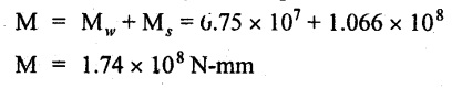
Result:
Total moment of resistance, M = 1.74 × 10⁸ N-mm
The corresponding maximum stress in steel, σbs = 200 N/mm2
Example 2.64:
A timber beam of rectangular section 250 mm deep by 75 mm wide is to be reinforced by steel strips 8 mm thick on both sides. The composite beam is simply supported at its ends 4m apart and carries a load of 8 kN is applied at the mid span. Find the maximum bending stress in the steel and timber at the mid span. Esteel = 2.1 × 10⁵ N/mm2; Etimber = 0.12 × 10⁵ N/mm2.

Given: Dimensions as shown in Figure.
Length, l = 4 m = 4000 mm
Load, W = 8 kN = 8 × 10³ N
Esteel = 2.1 × 10⁵ N/mm2
Etimber = 0.12 × 10⁵ N/mm2
To find:
σbs & σbt
Solution:
Maximum bending moment,
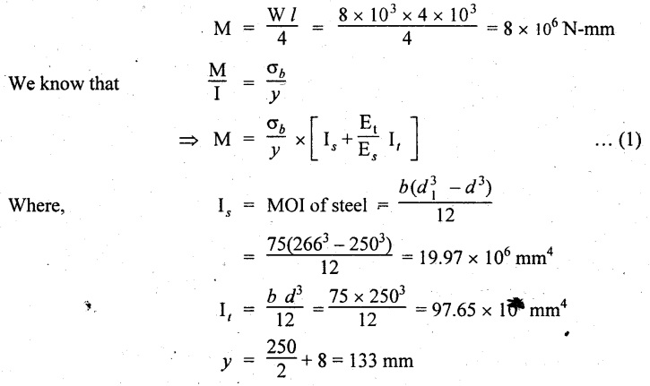
Substitute, M, y, Is, It, Et and Es values in equation (1)
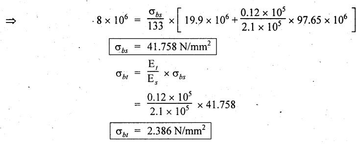
Result:
(i) Maximum bending stress in timber, σbs = 41.758 N/mm2
(ii) Maximum bending stress in timber, σbt = 2.386 N/mm2
7. UNIVERSITY SOLVED PROBLEMS ON THEORY OF SIMPLE BENDING
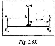
Example 2.65:
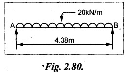
Find the dimensions of a timber beam of span 4.38 m to carry uniformly distributed load of 20 kN/m, if the width of the joist is half the depth and permissible bending stress is limited to 9 Mpa.
Given:
L = 4.38 m
UDL, w = 20 kN/m
Width, b = ½ depth, d i.e., d = 2b
Bending stress, σb = 9 Mpa = 9 N/mm2
To find:
Dimensions of a timber beam (i.e.,) (b and d)
Solution:
For the SSB as shown in Fig.
The maximum BM is given by,
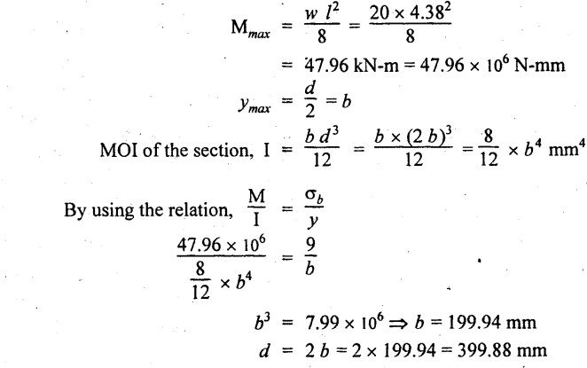
Result:
Dimensions of the beam, Width, b = 199.94 mm
Depth, d = 399.88 mm
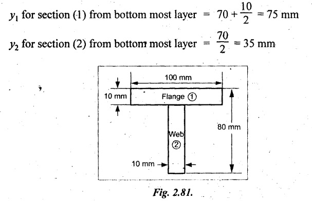
Example 2.66:
A T-section of a beam has the following dimensions. Width of the flange 100mm, overall depth 80 mm, thickness of the web 10 mm, thickness of flange 10 mm. Determine the maximum bending stress in the beam, when a bending moment of 200 N-m is acting on the section.
Given:
Bending moment, M = 200 N-m
= 200 × 103 N-mm
Area of section (1), a1 = 100 × 10
= 1000 mm2
Area of section (2), a2 = 70 × 10 = 700 mm2
To find:
Maximum bending stress, σb
Solution:
For unsymmetrical section, the centre of gravity of the section is placed 'y' mm from the bottom face. They may be calculated by using the following formula.

y = 58.53 mm
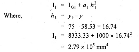
Moment of inertia of rectangle (1) about an axis through its C.G. and parallel to X-X axis.

From parallel axis theorem, MOI of rectangle (1) from X-X axis.
Similarly for section (2),

Now, moment of inertia of whole section about X axis
Ixx = I1 + I2
= 2.79 × 10⁵ + 6.73 × 105
= 9.52 × 105 mm4
By using the relation,

Result:
The maximum bending stress, σb = 12.29 N/mm2 or Mpa
Example 2.67:
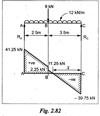
A simply supported timber beam of span 6m carries a UDL of 12 kN/m over the entire span and a point load of 9 kN at 2.5m from the left support. If the bending stress in timber is not to exceed 8 N/mm2, design a suitable section for the beam. The depth of beam equals twice the breadth.
Given:
l = 6 m
UDL, w1 = 12 kN/m
Point load, W = 9 kN
Bending stress, σb = 8 N/mm2
d = 2 b
To find:
Depth and breadth
Solution:
Taking moment about A,

SF Calculation:
SF at C = - RC = -39.75 kN
SF at B (without point load)
= - RC + 12 × 3.5 = - 39.75 + 42 = 2.25 kN
SF at B (with point load)
= 2.25 + 9 = 11.25 kN
SF at A = RA = 41.25 kN
From SFD, the SF changes its sign at a distance of 'x' m from C. Therefore, the maximum BM lies at that point.
Maximum BM calculation:
The SF equation at that point is,
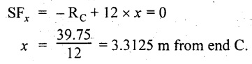
Therefore maximum BM,
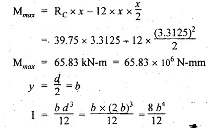
By using the relation,

Result:
Dimensions of the beam, Width, b = 231.12 mm
Depth, d = 462.24 mm
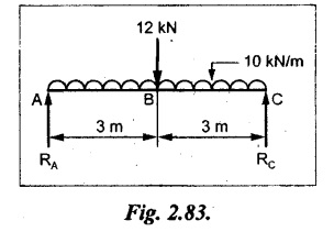
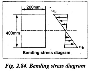
Example 2.68:
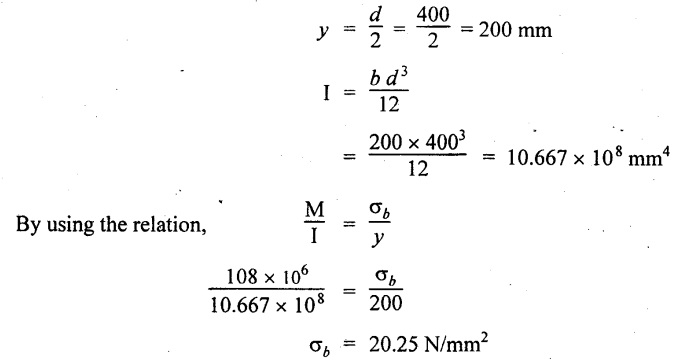
A rectangular timber beam of span 6m and cross sectional dimensions 200 × 400 mm is freely supported at the ends. It carries a UDL of 10 kN/m run for the entire span and a concentrated load of 12 kN at the center. Find the maximum bending stress and draw the bending stress diagram.
Given:
Width, b = 200 mm
Depth, d = 400 mm
To find:
Bending stress, σb and bending stress diagram
Solution:
The given beam is symmetric about Y-Y axis, therefore the maximum BM is acting at center.
Taking moment about A,
Since the beam is symmetric about Y-Y axis.
Therefore the maximum BM,
Mmax = RC × 3 = 36 × 3 = 108 kN-m
= 108 × 106 N-mm
Result:
The maximum bending stress, σbmax = 20.25 N/mm2
Example 2.69:
Calculate the maximum bending stress and shear stress in a cantilever beam of span 6m which carries a uniformly distributed load of 5 kN/m over a distance of 4 m from the free end. The cross section of the beam is a rectangle of breadth 100 mm and depth 150 mm.
Given:
l = 6 m
UDL, w = 5 kN/m
Breath, b = 100 mm
Depth, d = 150 mm

To find:
Maximum Bending stress and shear stress (i.e.,) σbmax and qmax.
Solution:
Maximum bending stress:
For the given cantilever beam, the maximum BM is acting at fixed end.
Therefore the maximum BM,

Maximum bending stress, σb = 106.67 N/mm2
Maximum shear stress (Refer next chapter - Shear stress distribution)

Result:
The maximum bending stress, σb max = 106.67 N/mm2
The maximum shear stress, qmax = 2 N/mm2
Example 2.70:
A round bar 8 cm diameter is to be used as a beam. Find the maximum allowable bending moment, if the stress due to bending is limited to 140 N/mm2. Calculate also the radius of curvature at the point of maximum bending moment if E = 210 kN/mm2.
Given:
Diameter, d = 8 cm = 80 mm
Bending stress, σb =140 N/mm2
E = 210 kN/mm2
= 210 × 103 N/mm2
To find:
(i) Bending moment, M and
(ii) Radius of curvature, R
Solution:

Radius of curvature, R = 60 × 103 mm
Result:
Maximum bending moment, M = 7 × 10⁶ N-mm
Radius of curvature, R = 60 × 103 mm
Example 2.71:
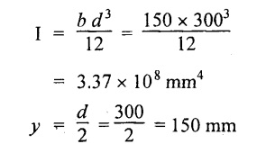
A beam 150 mm wide and 300 mm deep is simply supported over a span of 6 m. Find the maximum UDL the beam can carry if the bending stress is not exceed 8 N/mm2.
Given:
Width, b = 150 mm
Depth, d = 300 mm
l = 6 m = 6000 mm
UDL, L = 'w' N/m
Bending stress, σb = 8 N/mm2

To find:
Maximum UDL the beam can carry.
Solution:
Maximum BM for simply supported beam carrying UDL throughout the length,
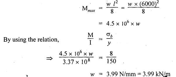
Result:
The maximum UDL the beam can carry, w = 3.99 kN/m
Example 2.72 :
A simply supported beam is subjected to a bending moment of 5 kN-m. The cross section of the beam is as shown in Fig. Sketch the bending stress distribution across the cross section.
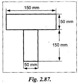
[This problem is similar to university solved problem, Example 2.66]
Example 2.73:
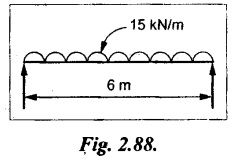
A simply supported beam of span 6 m is subjected to UDL of 15 kN/m over its entire length. The cross-section of beam is 20 cm wide and 30 cm deep. Sketch the variation of bending stress and shear stress in the beam cross section.
Given:
Width, b = 20 cm = 200 mm
Depth, d = 30 cm = 300 mm
w = 15 kN/m = 15 N/mm
l = 6 m = 6000 mm
To find:
To draw bending stress and shear stress distribution.
Solution:
Bending stress calculation:
Maximum BM, for simply supported beam carrying UDL over entire length is,
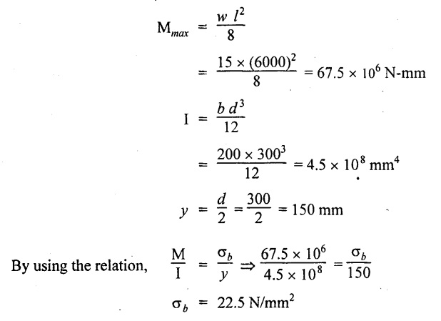
Shear stress calculation:
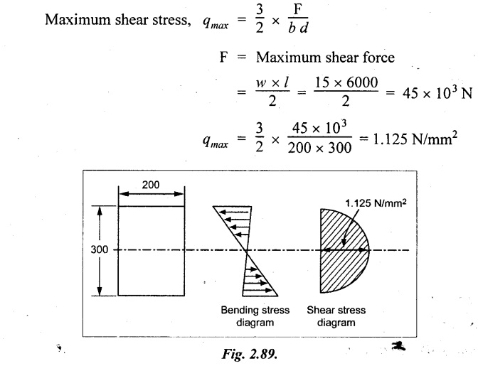
Result:
The bending moment diagram and shear stress diagram are as shown in Fig.2.89 respectively.
No comments:
Post a Comment