Showing posts with label Electrical Informations. Show all posts

Saturday, June 15, 2024

Why does an AC motor need a capacitor to start?

Not all AC motors need capacitor. And in some cases, capacitor is need not only at start up but while the motor is running too


No matter AC or DC, to turn the rotor of a motor, we need a thing called circular (or spinning/rotary) magnetic field with a torque/turning momentum. In AC net, we have 3 ways to make that: use 3 phases source, capacitor or short-circuit ring.

3 phase solution is used for “big” motors, where they have enough space to implement. It is the best solution in term of power efficiency. Furthermore, this solution is the only one that is cheap enough to provide big power force that two other solutions, due to the economic constrain (price/efficiency ratio) could not be used.

Short-circuit ring solution is the simplest then cheapest solution but the efficiency on power consumption is also the worst.

The capacitor solution is more compact than 3 phase and more power efficiency than the short circuit ring. Then for a small motor like your fan - not quite big to implement the 3 phase solution - and in a not so poor market - when we do not need the cheapest solution, the capacitor is used. Note that this solution could not be used for a big motor because a big capacitor would be too much expensive to create.

There are always two paths in an AC motor using capacitor. A capacitor needs time to charge then delays the phase angle of the current running through the path having this capacitor, compared to the current running in the other path - main working path. As each path generates itself an electro-magnetic field, this difference makes two different electro-magnetic forces, creating a torque to turn the rotor.

Without this capacitor, two currents in two paths have the same phase angle and no torque exists in this case, then rotor does not turn at all.

By the way, 3 phase solution has naturally this phase angle difference. Each phase has a 120 degree gap over the others.

And short circuit ring creates a shaded pole with an inductive winding of only 1 ring. This inductive winding generates an inductive current with the current phase angle also later than the angle on the main winding. Then makes also phase angle difference like two other solutions.


Return to the capacitor solution. If the rotor inertia could not keep the circular magnetic field alive, we need to keep a certain capacitor in the line. This capacitor is about 1/4 to 1/3 of the need at start up. In other case, the capacitor only needs to work at start up. After the rotor started to turn, the rotor inertia can keep the circular magnetic field alive then we do not need the capacitor anymore.

That is why in this case (the rotor inertia is big enough), when the capacitor dies, you can start your fan, after plug it into the wall power socket, by turning the fan blade manually.

That is also why many AC motors using capacitor have a mechanism to cut the capacitor path from the power line after the start up. The capacitor path is useless now but still consumes electric if not cut off. Using an inertia ball (centrifugal) switch is the simplest solution.

P/S: There is one more case that capacitor is used while the motor is running but not just only in start up. That is to improve the power factor of the motor. 

Electric motor is an electric device working based on electro-magnetic field. It then naturally creates an inductive reactance that reduces the motor power factor - power consumption efficiency. To reduce the total reactance of the motor - restore the “nearly ideal” value, a “working” capacitor is used.

But not like in the case that the rotor inertia is not enough, in which the capacitor is on the capacitor path, the power correction capacitor is almost in the main power line, before the point that the main line is separated to two paths for capacitor line and main working line or after the point of regrouping of these two paths

Monday, May 6, 2024

Why Does An Electric Tester Not Work On DC Current?

An electric tester is a device that detects the presence of voltage in a wire or an outlet.

It works by sensing a small amount of current that is capacitively coupled from the live circuit to the tester and back to ground.

The tester has a neon lamp that glows when it receives enough voltage, usually around 80 volt.an electric tester does not work on DC current because capacitors and transformers, which are used to couple the current, do not work with DC.

DC current has a constant polarity and does not change direction like AC current. Therefore, the tester cannot detect any voltage difference between the live wire and the ground.

If you want to test a DC circuit, you will need a different device, such as a multimeter, that can measure the actual voltage level on the wire. A multimeter can also measure other electrical properties, such as resistance and current.

However, you should be careful when using a multimeter on a live circuit, as it may cause a short circuit or damage the device if you use the wrong settings or probes.

Always read and follow the instructions and warnings that come with your multimeter before using it.

Monday, April 1, 2024

What is the maximum voltage a human can withstand?

I am surprised at the low quality of answers given here! Sorry to say, nearly all of the answers display a tenuous grasp of electronics and electrical nature, and use the age-old adage “it’s not the voltage, but the current that kills.” So I’ll clear things up, and hopefully save some people from misunderstanding this any further.

VOLTAGE, CURRENT, AND POWER

Voltage is related to the electric force between two points. More specifically, it is the gradient of the electric field, which in turn is a description of electric force. It is a description of electric potential energy, the ability of the electric field to force a charged particle and move it (i.e. the ability to do work). Because electric force exists between electric charges, voltage can also be interpreted as related the difference in charge between two points. Any time there is a voltage between two points, there must also be an electric field, though the electric field will actually depend on the physical distance between the two points.

When an electric field exists in an imperfect conductor, a current will flow in the conducting medium. Current is the movement of charged particles (electrons, ions, etc). In order for charges to circulate in a loop, a power source is required which might maintain the potential difference (the voltage) between two points by, we could say, ‘rearranging’ the charges: a voltage source. It could also maintain a constant flow of current: a current source. Either way, a potential difference (voltage) in an imperfect conductor will always cause a current. In imperfect conductors, the current will have many, many interactions with the conductor’s atoms. It’s like playing Plinko. This will then give more kinetic energy to the conductor’s atoms, and heat is generated. So any time a current flows in an imperfect conductor, heat is generated.

With these simplified definitions of voltage and current, we can look at some scenarios that will help clear up some of the confusion. If there is a voltage between two points, it means there is a difference in the quantity of charge between those points. This applies anywhere. If the charge difference is between two conductors, say a human hand and a doorknob, the charge difference will cause an “equalization”. Many charges will be moved very quickly because they are under a great force (by nature of there being a voltage). This is a current, but it is limited to the difference in charge between the two points. Once all the charges are moved, there’s no more current.

The voltage in this scenario is only dependent on the difference in the quantity of charges, but it can get into the thousands of volts, the kilovolts (kV). The limited quantity of charge that can possibly be moved, however, means this voltage is reduced to 0V very, very quickly, and the current flow is quite brief.

If, on the other hand, you have a power source, such as a voltage source, the potential difference will be maintained. The current that flows will be proportional to the resistance of the path, as long as the power source can supply enough current. That is key: Every power source can only supply current up to a point, called the rated current. So a AA battery, for example, can supply currents up to, maybe, 1A (1 ampere). You have to put it across a resistance that will not exceed this. If the “load”, the conductive/resistive path between the + and the -, is too low resistance, the battery’s internal resistance will limit any more current from flowing.

Voltage sources are much more common for the average consumer, so current sources we’ll leave by the wayside. Voltage sources include things like batteries and wall outlets. You can have constant voltage, which produces constant current, or direct current (DC), or voltage that changes continuously from a positive value to a negative value, producing a current that moves forwards and then back, over and over - an alternating current (AC). This is really only included in this description for completeness.

Anyway, all voltage sources have a rated current. If you exceed it, the voltage will simply get lower instead of the current increasing any more. For the voltage of the source, V, and the maximum suppliable current, Imax, we say the power of the source is P = V*Imax.

The power of a source is constant. Or at least ideally. If you convert the voltage to a higher voltage, the maximum current must decrease. If you want to convert the output to get more current, the voltage output will go down. Whatever you do, the product of the voltage and the max current will stay constant.

For example, given a AA battery with a voltage of 1.5V and a rated max current of 1A, the power is 1.5*1 = 1.5W. We can know “step up” the voltage from the battery (using a clever circuit called a switch mode convert) from 1.5V to as high a voltage as we want. Let’s put the voltage to 5kV (5,000 V) because that’s a very high and seemingly dangerous voltage. But we know the power is constant, at 1.5W, so the maximum possible current our circuit will be able to supply will be 1.5/5000 = 0.0003 = 300uA (300 microamps). After 300uA, the supply voltage will simply drop instead of supplying any more current, just as before.

This is a failure of the power supply, and the actual applied voltage will drop, so the load isn’t actually seeing the 1.5kV after you try to pass 300uA. Power supplies with higher power ratings will be able to source more current, supplies with lower ratings will be able to generate still less current, before they all hit their limit.

Side note: switching converters, or any voltage converter for that matter, will always have an efficiency rating. If you supply it with 1.5W, it might only be able to supply 85% of that, 1.2W.

MAN VS ELECTRICITY

Now we can talk about what happens when a current flows through a person. As was mentioned, current flow always generates heat. The more current, the more heat. The human body has a fairly high resistance, but not as high as one might think. To get current to flow requires a power source with a voltage that is fairly high, because we’re forcing the current through a lot of resistance. Here’s a familiar chart of what happens to a person at different currents.

The current passing through your body will be generating a lot of heat, enough to burn your insides. It will also mess with your nervous system, limiting your ability to control your muscles. The amount of current that can kill is rather low, at around 100mA+. The resistance of the human body is roughly between 100k and 1k, or 100,000 and 1,000 ohms. In the chart you can see the voltage required to get the corresponding current levels to pass through a human body at either side of the spectrum.

Now, knowing what we know about power, we see that a deadly amount of current will pass at between 100V and 10kV at 100–300mA, which would require a power supply that is not only at a voltage of 100V–10kV, but is also capable of supplying between 10W and 1kW (1,000W). If the power supply satisfies both conditions, you will be in danger. If it has a rated power of <10W, you’ll never be at risk, because either the voltage will drop (and thus the force causing the current is reduced, and the current will reduce) or the current will simply be too low to cause death. Assuming you fit in the 100mA part of the current survival threshold, anyway.

CONCLUSION AND OTHER CONSIDERATIONS

So what voltage can a person survive? Well if we’re considering death from heat, burning, and tampering with vital organs, it’s going to be between 100V and 10kV, as long as the power supply can actually produce the current that would kill you. An ideal, limitless power supply will always be deadly between 100V and 10kV, but in the real world there are always power limits.

This seems to imply that the human body can withstand any voltage, as long as the source of the potential difference (e.g. a difference in amount of charge) can’t produce currents high enough to burn you and disrupt your organs. Even if you have a voltage of 100MV (100,000,000V) between you and something else, you should be perfectly alright as long as no current can flow through you. Right?

This is actually interesting because I can’t say for sure that the human body will always be alright as long as the voltage difference is caused by something that can’t really supply current. If, for example, there are two 10ft square plates with a voltage of 100MV between them, and there’s no arcing or anything, and you’re between them, your body resistance should allow for a significant potential difference across you from the side facing one plate to the side facing the other. When that happens, the charges in your body will naturally want to reorient themselves, and I don’t know what risks you would face when this happens. Maybe you would see no change, maybe you would lose brain function and your heart would stop, but I would think the former to be more likely. I’d have to really think about it.

Anyway, let’s finish up by replacing “It’s not the voltage that kills you, it’s the amps!” with “Death by electrocution requires a high voltage power supply that has a rated power which allows for 100mA or more of current to flow under load.” It’s catchy, I guess.

Sunday, March 31, 2024

How does power factor affect the electricity bill for a home?

This is a complex topic to explain. I will try to keep it simple.

Certain loads connected to the AC supply are inductive in nature. Inductive loads react with AC (called inductive reactance) They oppose a change in current and since AC is always changing they cause the current to lag behind the voltage by some amount of electrical degrees. This is called inductive reactance.

Loads like motors and gas discharge lamps like fluro’s, mercury vapour lamps and sodium vapour lamps are inductive due to the ballast or chokes used in the circuit. Between all these they form by far the great majority of electrical loads connected to the grid. Particularly motors. The waveforms produced looks a bit like the one circled in red pen where the current is lagging behind the voltage. The ideal is circled in blue pen.


This causes problems for the power metering because the meters do not measure the amount of energy use accurately. the watt/ hour meters will read less tan they would normally.

The out of phase relationship can be represented by a vector diagram and a right angle triangle shown below. A very poor power factor will show a large angle and the power factor is the cosine of that angle. It is between 0 and 1 lagging.

A poor power factor doe not affect the home electricity bill much because most loads that produce a poor power factor have inbuilt power factor correction already fitted or are relatively small loads compared to industrial loads.

Large industrial installations often have power factor problems because they have many large electric motors. So they may need to use one of various methods to correct this.

Capacitors have the opposite effect to AC and so they are often used to correct the power factor to a reasonable or acceptable power factor that is determined by the supply authority..

Saturday, March 30, 2024

Why aren’t ultra high voltage transmission lines insulated?

They are insulated, by 10 or 20 feet of air, and by glass insulators at every support point.

They don’t use conventional PVC or thermoplastic insulation like low voltage wiring because

  • up in the air they are protected from accidental contact
  • thermoplastics will break down from UV exposure and have to be replaced periodically - a high maintenance cost. Air is free, no-maintenance, and lasts for ever
  • ultra HV will require hugely thick and costly insulation to insulate it.
  • insulation adds cost not only for the insulation but also because the wires become heavier and need to be stronger to support the weight, and the towers then need to be closer together, etc.
  • cladding Insulation degrades the thermal performance. Bare wire has the highest heat dissipation, clad wire is usually thermally insulated and the I-R drop heats the wire increasing resistance and lowering power carrying capacity; bare wire has the highest thermal performance.

Wednesday, March 27, 2024

Batteries in Series or Parallel for Power Applications?

Batteries in series connection adds voltage.

Batteries in series connection adds voltage.

Batteries in parallel connection adds current capacity and Amp Hr capacity

Combination series and parallel adds both voltage and current an Amp hr capacity to what ever is desired.

Batteries should be the same type, age, state of charge, capacity in current and voltage for best results and longevity.


How does an AC motor work?

An AC (alternating current) motor is a type of electric motor that operates on alternating current. AC motors are widely used in various applications, from industrial machinery to household appliances. They work by converting electrical energy into mechanical energy, thereby creating rotational motion.

There are several types of AC motors, but one common type is the "synchronous" and "asynchronous" motors. Let's focus on the asynchronous motor, also known as the induction motor, which is the most commonly used type.

Here's a simplified explanation of how an asynchronous AC motor works:

  • Stator: The stationary part of the motor is called the stator. It consists of a set of coils arranged in a circular pattern. These coils are connected to an AC power supply.
  • Rotor: Inside the stator, there is a rotor, which is the moving part of the motor. The rotor can be either a cage rotor or a wound rotor, depending on the design of the motor.
  • Principle of Induction: When AC voltage is applied to the stator coils, it creates a rotating magnetic field. This rotating magnetic field induces a voltage in the rotor due to the principle of electromagnetic induction.
  • Induced Current: The induced voltage in the rotor windings causes an electric current to flow. This current generates its own magnetic field.
  • Interaction of Magnetic Fields: The magnetic field of the rotor interacts with the rotating magnetic field of the stator. This interaction creates a torque that tries to align the rotor's magnetic field with the rotating stator field.
  • Rotation: As the rotor tries to catch up with the rotating stator field, it begins to rotate. However, due to the design of the motor, the rotor can never quite catch up to the speed of the rotating stator field. This difference in speed between the rotor and the stator field is called "slip."
  • Output Motion: The rotational motion of the rotor is then transferred to a mechanical load, such as a fan, a conveyor belt, or a pump. The motor's design and construction ensure that this rotational motion is continuous and efficient.

It's important to note that AC motors are versatile and can be designed to provide various levels of power and efficiency. They are commonly used in situations where a constant speed is required. They are also relatively simple, durable, and cost-effective, which makes them suitable for a wide range of applications.

Monday, March 25, 2024

How do I convert a 230v AC to a 110V DC?

Converting 230V AC (Alternating Current) to 110V DC (Direct Current) involves a two-step process: transforming the voltage level and rectifying the current type. This conversion is commonly required for operating equipment that requires 110V DC and is essential in various electrical applications. The first step in the conversion process is to reduce the AC voltage from 230V to 110V.

This is achieved using a step-down transformer, which adjusts the voltage through electromagnetic induction. The transformer's primary coil receives the 230V AC, and its design ensures that the secondary coil outputs the desired 110V AC. Once the voltage is stepped down, the AC needs to be converted into DC. This is done through a process called rectification.

A rectifier, typically a bridge rectifier, is used for this purpose. It consists of diodes that only allow current to flow in one direction, thus converting the alternating current into direct current. However, this DC is not pure and contains ripples. To smooth out the ripples and achieve a stable 110V DC, a filter (usually comprising capacitors or inductors) is employed.

In some cases, a voltage regulator might also be used to ensure a constant voltage output.

 The combination of these components—step-down transformer, rectifier, and filter—allows for the efficient conversion of 230V AC to 110V DC.

Footnotes

Thursday, March 21, 2024

How do you prove Ohm's law using the classical free electron theory?


Let's see, Ohm's law is basically the idea that the current in a conductor is proportional to the voltage across it.

You know, V=IR and all that jazz.

But how do we explain this from a microscopic point of view? What's going on inside that metal when we apply an electric field?

That's where the classical free electron theory comes in.

This thing says that a metal is made of a bunch of positive ions in a lattice and a bunch of free electrons that can move around like gas molecules.

The electrons are constantly colliding with each other and with the ions, but we don't care about the electron-electron collisions because they don't change the net momentum or current.

The electron-ion collisions, on the other hand, are important because they make the electrons lose energy and change direction.

So, when we apply an electric field to the metal, the electrons feel a force that makes them accelerate in the opposite direction of the field.

But they don't go very far before they hit an ion and bounce off randomly.

This means that they have a very small average drift velocity in the direction of the current, which is proportional to the electric field.

The current density, which is the current per unit area, is then given by J=−nevd, where n is the number of free electrons per unit volume, e is the charge of an electron, and vd is the drift velocity.

Now, we can relate the drift velocity to the electric field by using some simple physics.

The force on an electron is 
= , where E is the electric field.

The acceleration of an electron is a=F/m, where m is the mass of an electron.

The time between collisions is t, which is also called the relaxation time. The drift velocity is then vd=at=−eEt/m/.

Putting it all together, we get J=ne2Et/m, which shows that the current density is proportional to the electric field.

This is the local form of Ohm's law.

To get the global form, we just integrate over the length of the wire and divide by its cross-sectional area.

We getV=IR, where R=m/(ne2tA), which is called the resistance.

……….

And there you have it. We just proved Ohm's law using the classical free electron theory.


Of course, this theory is not perfect and it has some limitations, but it's good enough for most purposes.

Saturday, March 9, 2024

Why should we use a star-star connection?

 OQ: 

For the most part you usually shouldn’t, except under special circumstances.

A star-star connection is a topology used to build a three phase transformer. Both the primary and secondary windings in the transformer are connected to their source and load lines, respectively, in a star configuration, also known as a Y, configuration. The other possibility is a the Delta connection. Here’s a diagram to make the difference clear:

The star connection gives you a true neutral (N) and always produces a four wire circuit. The delta connection is what Navy ships use. The delta topology does not give you a true ground, so one of the phases can short to ground (e.g. battle damage), which comes with a lot of fireworks and transient currents that pop breakers, but when things settle out again, you can reset the blown breakers, replace the bad fuses, and keep operating.

Stepping voltages up and down and moving electrical power around is always done with transformers that use one of these topologies: (star-star or delta-delta) or else mixes them in one of two ways (delta-star or star-delta) Each of these four transformer designs has advantages and disadvantages. But for the answer the question, we will discuss only the star-star.

Here is how a star-star transformer is wired:

|———————————— Source ———————————-|

| ———————————— Load ————————————-|

The star-star transformer’s advantages:

  1. The primary and secondary voltages are always in phase.
  2. The currents flowing through the primary windings is always the same as the currents in the source.
  3. The currents flowing though the secondary windings is always the same as the currents n the load.
  4. The voltage between the phases is always SQRT(3) * winding voltage
  5. The voltage of the Neutral wire is always zero volts with respect to ground, so long as the loads on the three phases is balanced.

The star-star disadvantages all rear their ugly heads when the load is not balanced. They are:

  1. If the load is unbalanced, N is never zero volts with respect to ground. In fact, N’s phase and voltage with respect to ground move around as a function of the unbalanced loads of each of the phases.
  2. If the load is unbalanced, the voltages of the three phases are unequal.
  3. If the load is unbalanced, this configuration generates a lot of radio frequency noise that interferes with nearby communication lines. For example, telephone lines can’t be run in parallel with lest inductive coupling ruin their signals.

In practice, loads are never very balanced. Because of that, the star-star configuration is just not used in common practice (but I don’t know anything about high tension long distance power transmission — never got involved in it).

EDIT: What are the special conditions where a star-star transformer might be preferable? When the load is always balanced! One example is stepping down high voltage to drive a 3-phase motor. The motor’s current will be proportional to load, and the stead-state current in the three phases is always equal due to the nature of 3-phase electrical motors.

Wednesday, March 6, 2024

Why Don’t Birds Sitting On Wires Get Electrocuted?

The reason birds don’t get electrocuted when sitting on power lines is because they are not completing the circuit that is required for electricity to flow. If a bird were to have one foot on the wire and the other foot on the ground or a different wire, the bird would be electrocuted because it would be acting as a conducting medium.


Characters in the movies often end up with a blackened face and frizzy hair after coming in contact with a live wire charged with electricity. As observers, we laugh our hearts out at these ridiculous moments, but in real life, a live wire won’t be so gentle. You’d end up with more than just frizzy hair, torn clothes, and a crooked face. The thousands of volts could kill you instantaneously – unless you’re a bird, that is.

It’s a very common sight to see birds perched on top of electric wires, almost mocking us with their ability to relax at such heights. Birds have no problem sitting, undisturbed, on the high voltage wires lining the roads, but it has nothing to do with them being birds. As you’ve probably also seen, squirrels can run along wires unscathed too!

So What’s The Explanation?

This is all due to the connections that they’re making, or rather, not making.

Electric current is simply the movement of electrons. For electrons to move from one point to another, they require an adequate potential difference between the two points.

Just like all types of energy, electricity pursues equilibrium (or balance). This means that electricity will flow from areas of high energy to low energy along the path of least resistance. For example, if the bird were to have one foot on the wire they’re standing on, and the other foot on the ground or a different wire with less voltage, the bird would be electrocuted. This is because the bird would be acting as a conducting medium that allows the electric current to pass from the high voltage substance (wire) to the low voltage substance (ground).
When a bird is sitting happily on top of a wire:

(1) The circuit is incomplete, so the flow of electrons required to conduct electricity is hindered.

(2) The potential difference between all points on the wire is zero

Similarly, if a person were to stand on top of a power line, he would also remain unaffected by the wire (the wire wouldn’t be able to sustain the person’s weight, which is why this is purely hypothetical). A person standing on the ground, however, completes the circuit, so the person is electrocuted when coming in contact with the wire.

If The Wires Are So Dangerous, How Do Workers Carry Out Maintenance Work?

Workers on power lines use strong insulating materials in their clothing, equipment, and bucket trucks. Insulating materials, such as rubber and asbestos, are materials through which electricity struggles to flow. Therefore, instead of passing through the worker, the electrons stay on the other side of his rubber gloves or rubber-handled tools.

Another technique when working on power lines is to hang beneath a helicopter. Since neither the worker nor the helicopter is connected to the ground (like those birds), the worker just has to make sure that he only touches one wire at a time.

Despite taking such precautions, electrical maintenance is one of the most dangerous jobs out there. Therefore, it’s probably a wise choice to just stay away from electrical wires unless you’re a trained professional… or a bird.

Why Does A High Voltage Wire Make A Noise?


As you know, high voltage lines consist of 2 wires that pass current. These wires create a magnetic field on top of each other, and these magnetic fields cause a magnetic force to act on the wires. Since the current passing is alternating, that is, it is variable, this force also changes constantly with the current. This variable force causes the wires to oscillate. Here is the buzz we hear from the oscillation of the strings.

It is based on alternating current. Alternating current varies according to the sine function (sine wave). So the main reason for this is the famous trigonometric function in mathematics, the sine function.

I call it sine sound.

i=imax.sin(ωt).�=����.sin⁡(ω�).

sound extractor devices work with different types of current. however, each sound has its own current wave. For example, the headphones you listen to music generate current waves according to the type of music and this electric current turns into sound. We often call it a loudspeaker. Let the function of the electric current of a music be expressed as M(x)�(�). Suppose there is a dam that generates electricity according to the function of this music. According to this assumption, high voltage lines will also make the sounds of that music. so strange noises would come from the electric poles. we would probably hear the electric poles singing.

In that case, if we run a speaker directly with alternating current, zzzzzz or rrrrrrr sounds will come from this speaker. This is the sound of the sine function. On the other hand, if we operate this speaker with battery, we will hear sssss sound or space sound. We know that batteries produce a straight/constant current. I am not a physicist and have not experimented with this. I just made these comments by taking advantage of the power of mathematics. Maybe i'm wrong, but I'll test this at home.


As seen in the image, you see electrical current waves of any music. Now how do we find the function that represents this? If we use the Newton interpolation method, we will not be very successful. Maybe we can do some approximation to this function. These waves you see are not regular like alternating current and constant current.

There is also the aspect of this that has to do with the light intensity. Take a good look at the lamp you see in your home. you will see the sine function there too.

I was very small indeed. I saw a lamp connected to the speaker and the power of the lamp was blinking according to the intensity of the sound. The lamp glowed brighter when the man shouted into the microphone, and turned off when the man was silent. What was that mysterious thing?That's when i realized that strange things happen in life.

Monday, March 4, 2024

What is the difference between earthing and grounding?

Earthing:

Earthing refers to the connection of electrical systems or equipment to the Earth's conductive surface. The purpose of earthing is to provide a safe path for electrical faults, such as short circuits or electrical leakage, to flow into the ground. Earthing helps protect people and property from electric shock and minimizes the risk of fire or equipment damage.

In an electrical system, earthing typically involves connecting the non-current-carrying parts of electrical equipment, such as metal enclosures or casings, to the Earth using conductive materials, like copper rods or metal plates. This connection creates a low-resistance path for fault currents to flow, enabling the protective devices, such as circuit breakers or fuses, to quickly detect and interrupt the fault, thereby preventing potential hazards.

Grounding:

Grounding, on the other hand, refers to the intentional connection of electrical systems or equipment to the Earth or a reference point in order to establish a common potential. Grounding is primarily used for signal reference, stability, and noise reduction purposes, rather than safety.

In electrical and electronic circuits, grounding provides a stable reference point for voltage measurements and helps minimize interference from external electromagnetic fields. It also serves to dissipate any static charges or voltage spikes that may accumulate in the system, helping to protect sensitive electronic components from damage.

Grounding is commonly achieved by connecting a circuit's reference point, such as the neutral conductor in an AC power system or the common ground in electronic circuits, to the Earth or a grounding electrode system. This helps maintain a consistent voltage potential across the circuit and facilitates the proper functioning of electrical and electronic devices.

Why do we return neutral to earth?

First, we have to debunk the assumption inherent in that question, which is that neutral does go to ground. It sometimes does, and sometimes does not, depending entirely on where you're working and what you're working on.

The National Electric Code (NFPA 70) requires that neutral and ground be bonded at the main service entrance for residential eletrical service. English translation: the ground bus and neutral bus in your main panel are solidly tied together (typically via a bonding strap). This is done in this and only this location! Bonding ground and neutral again elsewhere in the system will create parallel ground paths, which is very dangerous.

Now, for why the code requires this, we must get into a little bit of what each is designed to do. In a standard 120/240 residential service, each circuit will have 3 wires. A hot, neutral, and ground. Looking at them, it's easy to see that the hot and neutral are the same size and have the same insulation thickness while the ground wire is commonly bare (uninsulated) copper. That's because it is designed to do something different.

The hot wire is the path for current to flow from source (panel) to load (let's just say it's a convenience outlet).

The neutral wire is the return path for the current from the load. Electricity 101: electricity is created by the movement of charged particles, and that movement is because unbalanced electrons sense a path to ground, where they can become balanced again. Things in nature like to be balanced. Without a return path, there's no movement of electrons and thus no electricity. In a single phase branch circuit like our example, the current on the hot wire and neutral should be identical (unless we have some ground leakage, which is beyond the scope of this answer).

The ground wire is a low impendance pathway between things-that-might-become-energized-but-aren't-supposed-to-be (metal housings, copper pipes, steel structure, satellite dishes, and the like) and our grounding rod driven deep into the soil outside by the meter. When you wire in conduit using metal boxes, it's allowable to use the conduit bodies and boxes themselves as the ground. In houses you normally wire with romex and plastic boxes, and so a separate ground wire needs to be brought to each outlet.

So, what is the reason we connect ground and neutral? It's for safety. If you go to your main panel and remove the bond between ground and neutral, you have just created a system with a floating neutral, that is, a neutral that has no reference to earth ground. On the plus side, now you have a system where a ground fault (a specific type of short where the hot wire touches something grounded) does not trip a breaker. Sounds pretty awesome, right?! Except for the fact that in your system, when you get a ground fault, you don't know it. And, everything that is grounded may be energized up to system voltage. So, when you're washing dishes and your cat walks on the wet countertop (the countertop where your metal toaster also sits), zzzzzzaaaapp goes the kitty. Replace "kitty" with "toddler" and you can see why the NFPA went away from this type of grounding (believe it or not, they had a serious discussion about the merits of grounded vs. ungrounded for residential installations once upon a time).

Section 250 of the NEC deals extensively with grounding, and if you ever need to give yourself a headache or to fall asleep quickly, I highly recommend it.

If, by chance, you do read it at some point, you may notice that while the NFPA has all sorts of information about grounding requirements, they say very little about grounding on systems above 240 V. And that's because when you get above 240 V you're getting into engineered systems, where some poor electrical engineer is going to have to stamp design drawings and put his professional life on the line that his grounding design is both safe and effective. And indeed, it's common to see different types of grounding systems in industrial and commercial installations. Ungrounded, resistance grounded, and solidly grounded are all in use; sometimes all three at the same facility!

But for you, ground and neutral are connected at the main service entrance so that when you get a ground fault, you trip a breaker. It's a safety issue, with a minor secondary issue being improperly grounded equipment can be prone to premature failure.

Sunday, February 25, 2024

Why does a Capacitor allow AC but not DC?

A capacitor is two plates next to each other with a gap in between.

When you hook it up to a current, the plates will begin to accumulate charge until they are "full". This happens fairly quickly, but not instantaneously. If you're using DC current, the current will stop when the capacitor is fully charged. Current can't flow in between the gap of the plates.

AC current switches polarity continuously. It does this faster than it takes the capacitor to fully charge. Before the capacitor is "full", the polarity is switched and the capacitor will change the polarity of the plates as well.

Friday, December 29, 2023

Automatic Street Light Control Circuit using LDR

 Following is yet another simple Electrical/Electronics project for automatic street light control systems especially for students, newbies and hobbyists.

Features:

  • It is a dark detector circuit based on LDR and a transistor (BC-547 NPN) which automatically switches ON and OFF the street light system.
  • It automatically switches ON street lights when the sunlight goes below the visible region of our eyes. (e.g. in the evening after sunset). 
  • It automatically switches OFF the lights when sunlight falls on it ( i.e. on LDR ) e.g. in the morning, the sensor called LDR (Light Dependent Resistor) senses the light just like our eyes and deactivates the circuit.

Advantages:

  • The automatic operation of street light controlling systems help to reduce the energy consumption as compared to the manually operated street light controlling operations. This is because there is a delay in the earlier switching operations both in morning (during sunrise) and evening (during sunset).
  • On sunny and rainy days, ON and OFF time is noticeably differ which is one of the major disadvantages of using timer circuits or manual operation for switching the street light system.

Components Required:

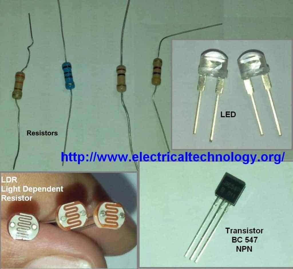
  • LDR – Light Dependent Resistor
  • 2 Nos. of transistors. (NPN transistor – BC547 or BC147 or BC548)
  • Resistor- 1kΩ, 100kΩ, 330 Ohm & 470 ohms.
  • Light emitting diode (LED) – Any color
  • Connecting wires – (Use single-core plastic-coated wire of 0.6mm diameter (the standard size) or any wire used in computer networking).
  • Power supply-6V or 9V

Procedure

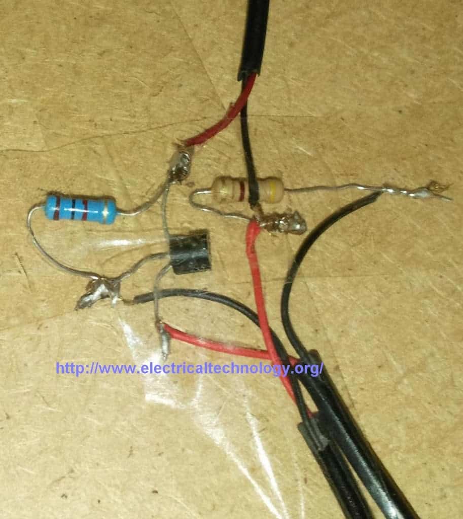
  • Insert first transistor Q1-BC547 (NPN) on breadboard (or general PCB) as shown in the circuit diagram 1.
  • Connect another transistor Q2- BC547 (NPN) on the breadboard as in step 1.
  • Connect  wires across the emitter pin of both transistors and -Ve terminal of battery (lowest/bottom row of breadboard.)
  • Connect  a wire across the Collector pin of transistor Q1 and Base pin of transistor Q2.
  • Connect a resistor 1K across the positive terminal of battery (topmost row of breadboard) and Collector pin of transistor Q1.
  • Connect  Light Dependent Resistor (LDR) across the positive terminal of battery (topmost row of breadboard) and base terminal of transistor Q1.
  • Insert a resistor- 330 Ohm across base pin of transistor Q1 and negative terminal of battery (lowest bottom row of breadboard).
  • Connect a resistor 330R across the positive terminal of battery (topmost row of breadboard) and anode terminal of LED (Light emitting diode) & Connect the cathode terminal of LED to Collector pin of transistor Q2.

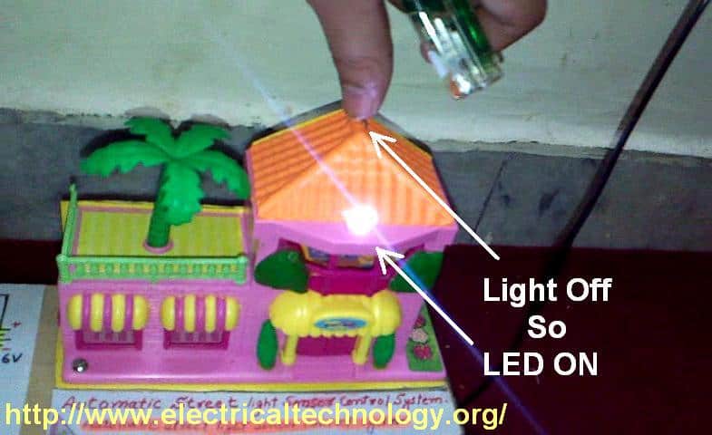
The simple circuit is ready for testing now. Connect 6V to 9V battery terminals to the circuit as shown in fig and see the output. As you block light falling on the Light dependent resistor(LDR), the LED glows and vice versa.

LED GLOWS EVEN IN LESS DARKNESS. Use torch light or lighter if the LED glows in less darkness. In addition, you can try to adjust the sensitivity of this circuit by using a variable resistor in place of R1-300 Ohm. You may use other resistances as well, (e.g., 1KΩ, 10KΩ and 100KΩ, etc.)

Pictorial Story: (Click images to enlarge)

Components & Schematic Circuit Diagrams for Automatic Street Light Control System

Automatic-Street-Light-Control-System

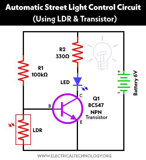
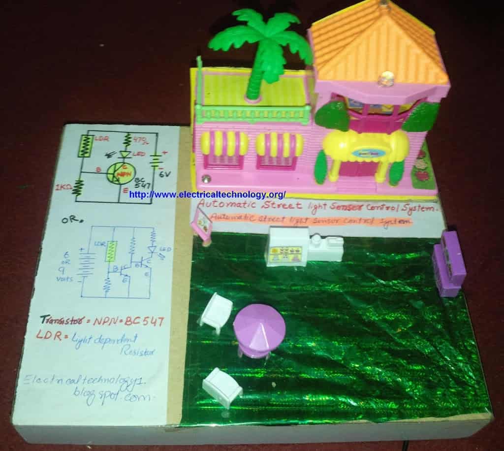
Circuit Diagram 1. Automatic Street Light Control System.(Sensor using LDR & Transistor BC 547.). We have tried and Cicuit#1 in this  tutorial but you may also try the second one (Circuit#2) mentioned below ight after circuit no 1.

Automatic Street Light Control Circuit using LDR & Transistor

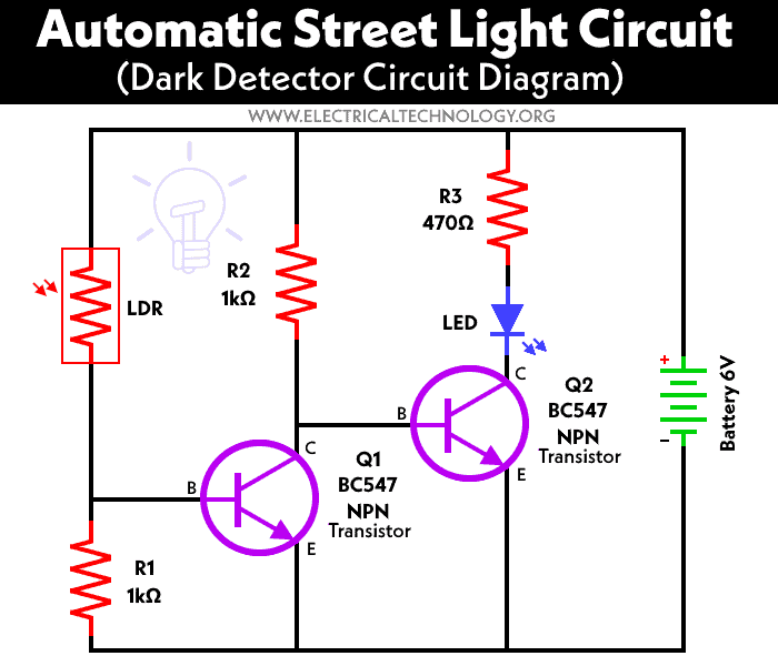
Circuit Diagram 2 . Automatic Street Light Control System using LDR and two nos. of Transistor BC 547.

Dark Detector Circuit for Automatic Street Light Control using BC547 Transistor and LDR

Automatic-Street-Light-Control-System.-2528Sensor-using-LDR-2526-Transistor-BC-547.-2529-Very-Simple
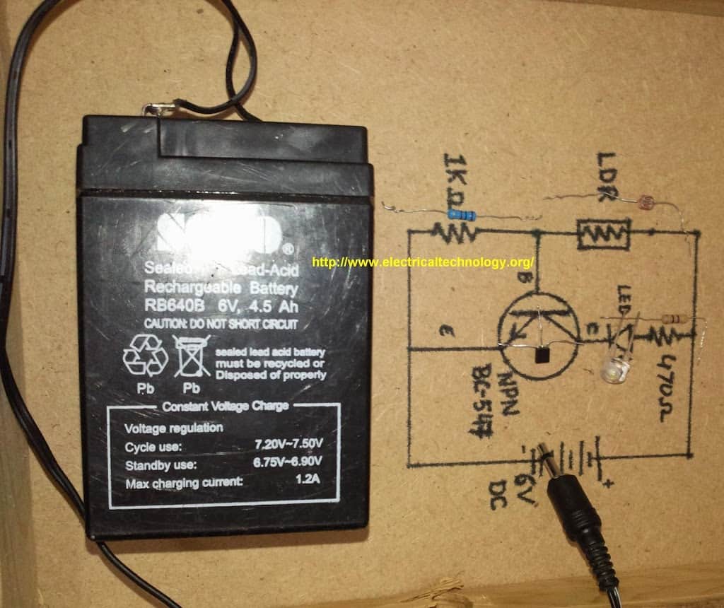
Automatic Street Light Control System.(Sensor using LDR & Transistor BC 547.) Very Simple.

Automatic Street Light Control System.(Sensor using LDR & Transistor BC 547.) Very Simple.
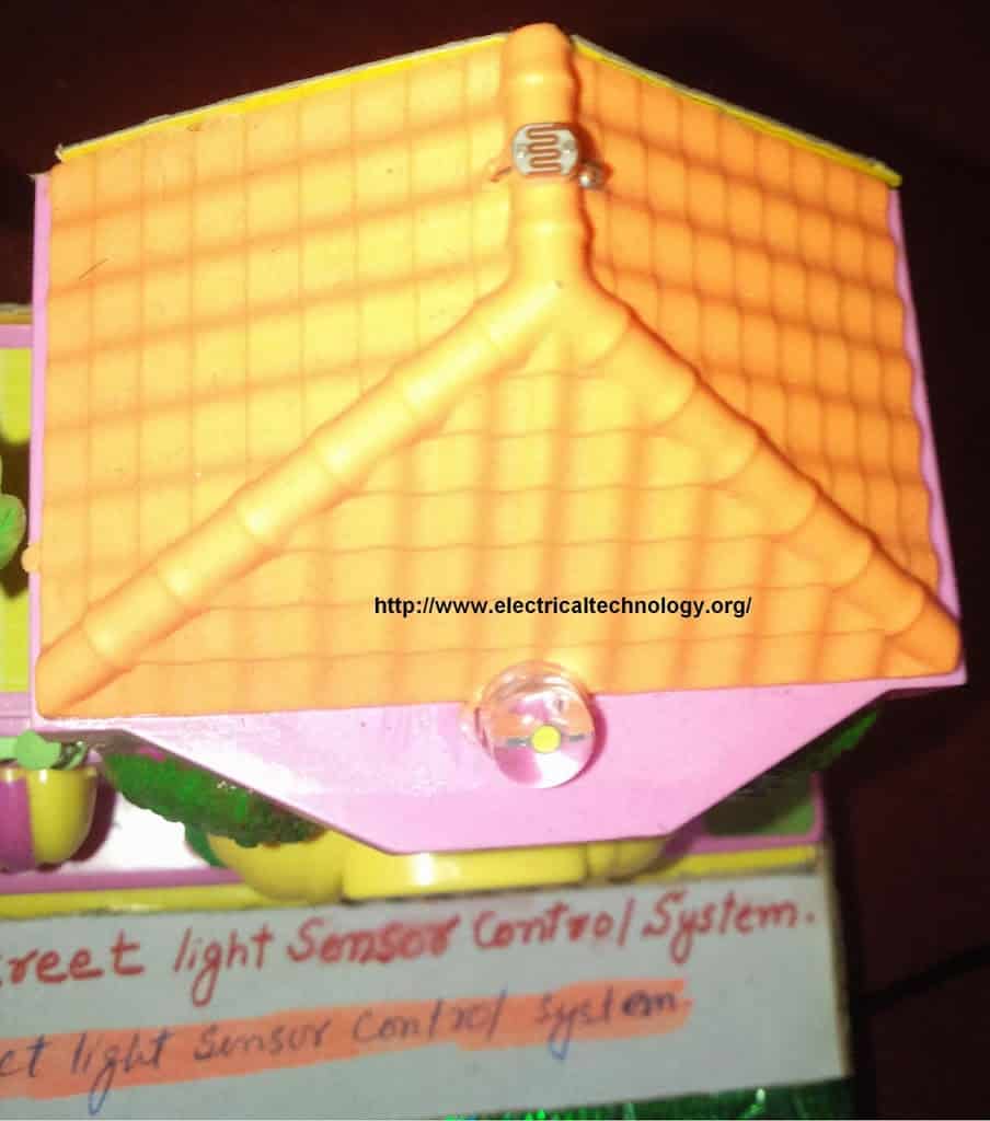
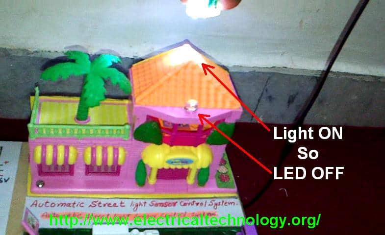
Whenever light falls on the LDR (Light Dependent resistor), the LED is OFF i.e. the LED does not glow.

Automatic Street Light Control System.(Sensor using LDR & Transistor BC 547.) Very Simple.

In the dark (e.g. when light is blocked to the LDR), the LED is ON i.e. the LED is ON.

Snapshot taken out from the Video.

Automatic Street Light Control System.(Sensor using LDR & Transistor BC 547.) Very Simple.

Some Basic Electronic Projects Circuit Diagrams based on LDR