Following is yet another simple Electrical/Electronics project for automatic street light control systems especially for students, newbies and hobbyists.
Features:
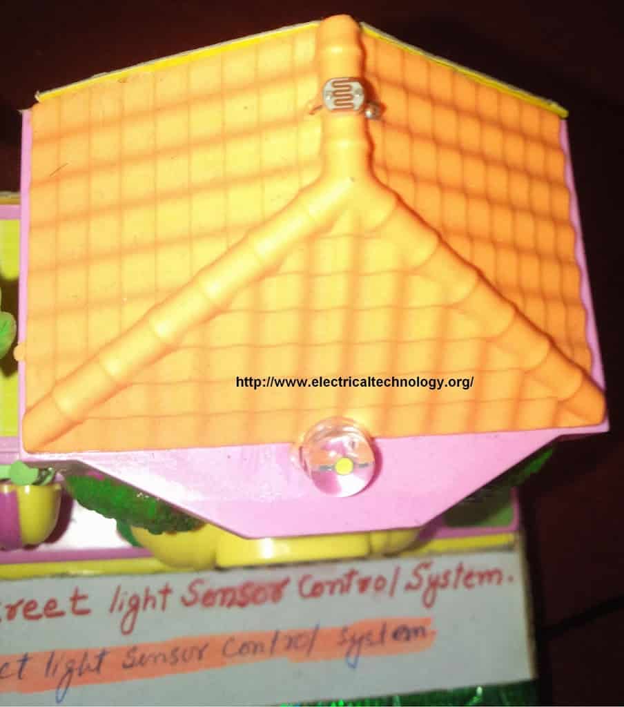
- It is a dark detector circuit based on LDR and a transistor (BC-547 NPN) which automatically switches ON and OFF the street light system.
- It automatically switches ON street lights when the sunlight goes below the visible region of our eyes. (e.g. in the evening after sunset).
- It automatically switches OFF the lights when sunlight falls on it ( i.e. on LDR ) e.g. in the morning, the sensor called LDR (Light Dependent Resistor) senses the light just like our eyes and deactivates the circuit.
Advantages:
- The automatic operation of street light controlling systems help to reduce the energy consumption as compared to the manually operated street light controlling operations. This is because there is a delay in the earlier switching operations both in morning (during sunrise) and evening (during sunset).
- On sunny and rainy days, ON and OFF time is noticeably differ which is one of the major disadvantages of using timer circuits or manual operation for switching the street light system.
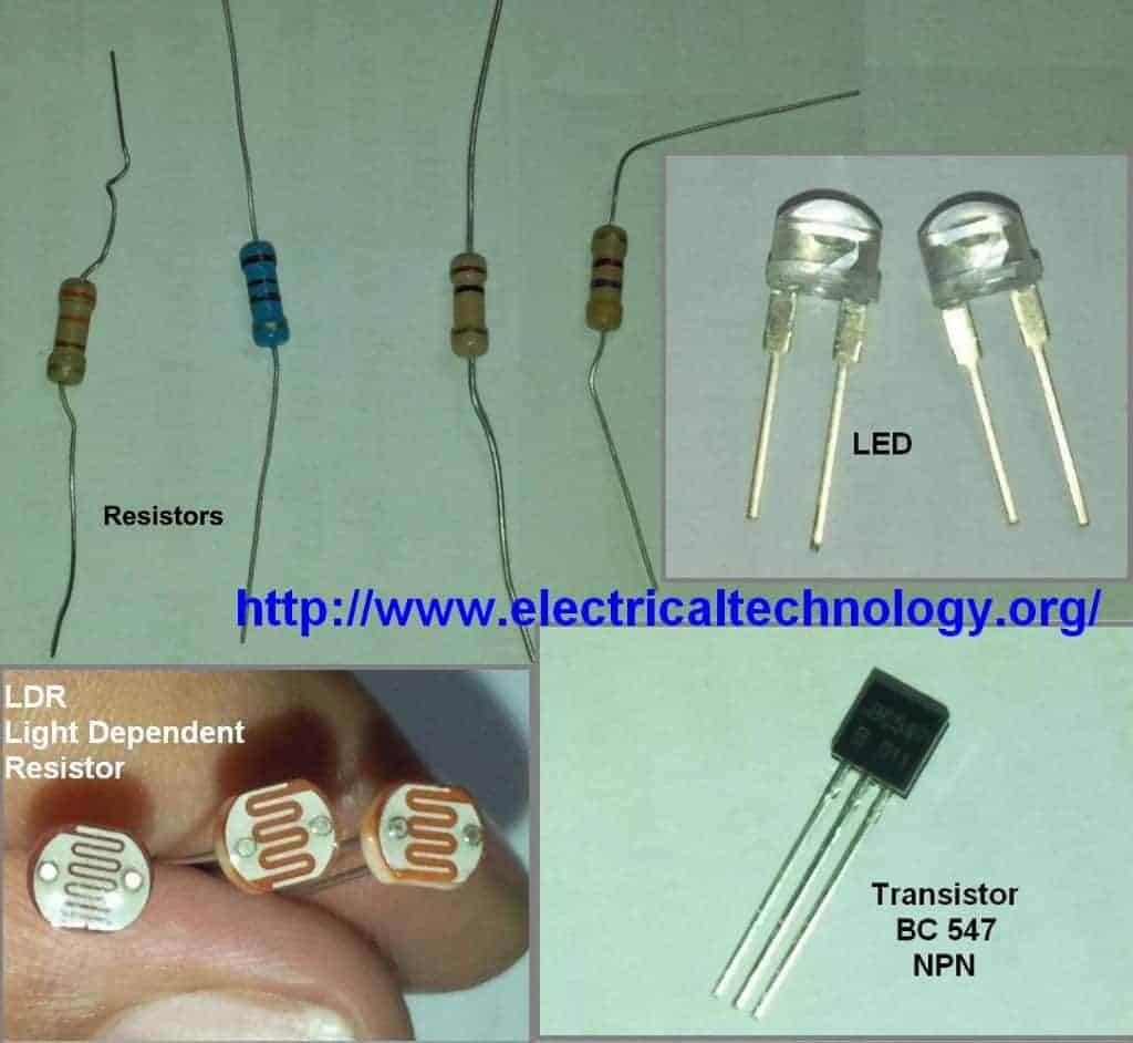
Components Required:
- LDR – Light Dependent Resistor
- 2 Nos. of transistors. (NPN transistor – BC547 or BC147 or BC548)
- Resistor- 1kΩ, 100kΩ, 330 Ohm & 470 ohms.
- Light emitting diode (LED) – Any color
- Connecting wires – (Use single-core plastic-coated wire of 0.6mm diameter (the standard size) or any wire used in computer networking).
- Power supply-6V or 9V
Procedure
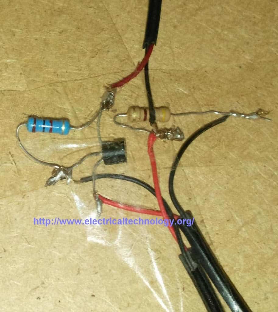
- Insert first transistor Q1-BC547 (NPN) on breadboard (or general PCB) as shown in the circuit diagram 1.
- Connect another transistor Q2- BC547 (NPN) on the breadboard as in step 1.
- Connect wires across the emitter pin of both transistors and -Ve terminal of battery (lowest/bottom row of breadboard.)
- Connect a wire across the Collector pin of transistor Q1 and Base pin of transistor Q2.
- Connect a resistor 1K across the positive terminal of battery (topmost row of breadboard) and Collector pin of transistor Q1.
- Connect Light Dependent Resistor (LDR) across the positive terminal of battery (topmost row of breadboard) and base terminal of transistor Q1.
- Insert a resistor- 330 Ohm across base pin of transistor Q1 and negative terminal of battery (lowest bottom row of breadboard).
- Connect a resistor 330R across the positive terminal of battery (topmost row of breadboard) and anode terminal of LED (Light emitting diode) & Connect the cathode terminal of LED to Collector pin of transistor Q2.
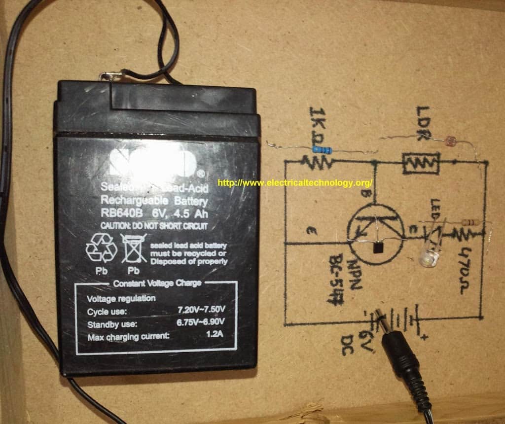
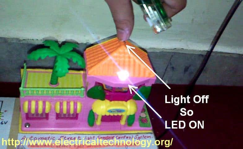
The simple circuit is ready for testing now. Connect 6V to 9V battery terminals to the circuit as shown in fig and see the output. As you block light falling on the Light dependent resistor(LDR), the LED glows and vice versa.
LED GLOWS EVEN IN LESS DARKNESS. Use torch light or lighter if the LED glows in less darkness. In addition, you can try to adjust the sensitivity of this circuit by using a variable resistor in place of R1-300 Ohm. You may use other resistances as well, (e.g., 1KΩ, 10KΩ and 100KΩ, etc.)
Pictorial Story: (Click images to enlarge)
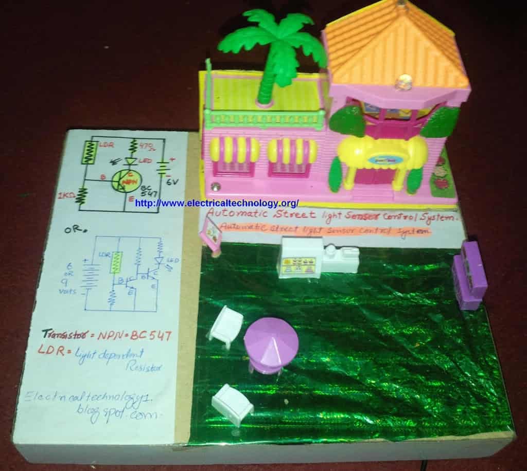
Components & Schematic Circuit Diagrams for Automatic Street Light Control System
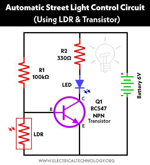
Circuit Diagram 1. Automatic Street Light Control System.(Sensor using LDR & Transistor BC 547.). We have tried and Cicuit#1 in this tutorial but you may also try the second one (Circuit#2) mentioned below ight after circuit no 1.
Circuit Diagram 2 . Automatic Street Light Control System using LDR and two nos. of Transistor BC 547.
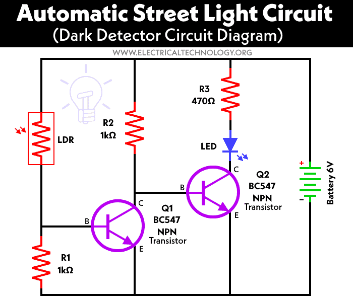

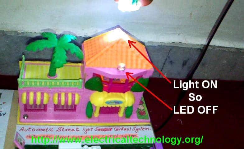
In the dark (e.g. when light is blocked to the LDR), the LED is ON i.e. the LED is ON.
Snapshot taken out from the Video.
Some Basic Electronic Projects Circuit Diagrams based on LDR
No comments:
Post a Comment