To remove very fine suspended and colloidal particles that do not settle in th sedimentation process. To remove dissolved impurities in water. To remove pathogenic bacteria from water.on (iv) To remove colour, odour, turbidity in water.
SAND FILTRATION
The process of passing the water through the beds of granular materials (filters) known as filtration.
Purpose of filtration :
(i) To remove very fine suspended and colloidal particles that do not settle in th sedimentation process.
(ii) To remove dissolved impurities in water.
(iii) To remove pathogenic bacteria from water.on (iv) To remove colour, odour, turbidity in water.
Types of filters:
(i) Slow sand filters
(ii) Rapid sand filters
(iii) Pressure filter
Theory of filtration:
During filtration, the following actions take place:
(i) Mechanical straining
(ii) Sedimentation
(iii) Biological action
(iv) Electrolytic action
(i) Mechanical straining (for coarser particles)
When water passes through the filter media (sand), the suspended particles larger than the pore-space of the filter media get trapped and removed. The trapped particles form a mat on the filter media and help in straining more impurities.
(ii) Sedimentation (for finer particles)
The voids of the filter media acts as small sedimentation tanks and fine particles giare removed by settling.
(iii) Biological action
Certain microorganisms and bacteria present in the voids of filters form coatings over the sand grains. These organisms utilize the organic impurities in water as their food and convert them into harmless compounds by biological metabolism. They form a layer on the filter media called "schmutzdecke or dirty skin". This layer further helps in absorbing and straining out the impurities in water
.(iv) Electrolytic changes (Ionisation)
The sand grains of filter media and impurities in water are oppositely charged. When the impurities come in contact with the sand grains, their charges get neutralised and changes the characteristics of water making it purer. After certain period of time, the charge of sand grains gets exhausted and should be restored by ge of s din cleaning the filters.
Filter Media:
Sand (fine or coarse) is generally used as filter media and supported on gravel.
(i) Sand:
The properties of filter sand are :
• It should be obtained from hard and resistant quartz or quartzite.
• Free from dirt and other impurities.
• It should not loose more than 5% of its weight when placed in hydrochloric acid (HCI) for 24 hrs.
• Specific gravity = 2.55 to 2.65
• Effective size (a) 0.2 to 0.4 mm - slow sand filters.
(b) 0.35 to 0.55 mm – rapid sand filters..
• Uniformity co-efficient
(a) 1.8 to 2.5 - slow sand filters
(b) 1.3 to 1.7 - rapid sand filters
The uniformity characteristics of sand are expressed in terms of
(a) effective size (b) Uniformity coefficient.
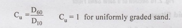
Effective size or diameter (D10) represents a size of sieve in mm, throuth which 10% of the particles will pass i.e.,are finer than this size. Similarly, D60 size represent a size such that 60% particles are finer than it.
Uniformity coefficient (Cu) is a measure of the particle range i.e. variations in size of particles.
(ii) Anthracite - Crushed anthracite can be used as filter media separately or combined with sand (mixed media). It is costly than sand.
(iii) Garnet sand - It has high specific gravity (4.2) and is a dense material. Due to high cost, it cannot be used as a sole filter material. However, it can be used in mixed-media 30 so filter.
(iv) Other materials - Locally available materials such as shredded coconut husks, burned rice husks, crushed glass, slag, metallic ores etc. can be used as filter material.
Slow Sand Filters (SSF)
The efficiency of slow sand filters is high and they can remove larger percentage of cy of slow and filterich 000 oval base to siziano T suspended impurities and becteria. The efficiency of bacteria removal is 98 to 99%.
These filters can also remove odours and tastes caused by organic impurities (algae and plankton). They are less efficient in removing colour and can remove turbidity only upto 50mg/1.
They are not suitable for sedimented waters with high turbidity.
The rate of filtration is less (i.e. 100 to 200 litres per hour per to rapid sand filters.
They also require large area of land and are costly to install.
Their use has therefore decreased and are preferred only in smaller water treatment

Construction of Slow Sand filters
A slow sand filter consists of the following parts:
(i) Enclosure tank
It is an open basin, rectangular and built below ground level. The water-tight tank is constructed of stone/brick masonry with coating of water proof material. The floor has bed slope -1 in 100 to 1 in 200 towards the central drains. Surface area of tank varies between 50 m2 to 1000 m2. Rate of filtration is - 100 to 200 litres of water per square meter. Depth of tank varies between - 2.5 to 4 m.
(ii) Filter media
It consists of Sand layer, 90 to 110 cm thick placed over gravel.
Effective size - 0.2 to 0.35
Uniformity coefficient - 2 to 3
Sand is placed in layers of 15cm, with finer sand on the top layer and coarser sand
(iii) Base material (Gravel)
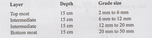
The base material is gravel, which supports the sand. It consists of 30 to 75cm thick gravels placed in three to four layers, each of 15 to 20 cm depth. The coarser gravel in the bottom layer and finest gravel in the topmost layer. The gravel size in different layers is given below:
Top 15 cm layer – Gravel size 3 to 6 mm
Intermediate layers - 6 to 20 mm / 20 to 40 mm
Bottom most 15 cm layer - Gravel size 40 to 65 mm
(iv) Under-drainage system
Filter media (sand) and base material (gravel) are laid over the under-drainage system. It consists of a central drain and lateral drains. Laterals are open jointed pipe or porous drains placed at 3 to 5m spacing on the bottom floor and sloping towards the central drain. Filtered water is collected by the laterals and discharged into the central main drain and then to the filtered water well.

(v) Inlet and Outlet arrangements
An inlet chamber admits water from the plain sedimentation tank and distributes over the filter media.
A filtered water well on the outlet side, collects the filtered water coming out from the main drain.
An adjustable telescopic tube in the outlet chamber maintains constant discharge through the filter.
Inlets and outlets are controlled by automatic valves.
(vi) Other appurtenances
* Vertical air pipe – is provided passing through the sand layers for proper functioning loving 192 of filtering layers. O
* Arrangements to control depth of water above sand layer (1 to 1.5m)
A meter is used to measure the flow and a gauge to measure the loss of head.
Operation and cleaning of Slow Sand Filters.
The treated water from the sedimentation tank is allowed to enter the inlet chamber of the slow sand filter and get distibuted uniformly over the filter bed. The water percolates through the filter media and gets purified during filtration. The water then enters the gravel layers and comes out as filtered water. It gets collected in the laterals (porous pipes), which discharges into the central main underdrain and finally into the 'filtered water well'. The filtered water is then taken to storage tanks for supply and distribution. The rate of filtration is kept constant by the telescopic tube.
The water entering the slow sand filter should not be treated by coagulants, because it may affect the formation of 'dirty skin or Schmutzdecke layer' and the functioning of the filter.
The depth of water above the sand layer should be kept equal to the depth of filter sand.
The loss of head called filter head or filtering head is limited to a maximum value of 0.7 to 1.2m. It is the difference of water levels between the filter tank and filtered water well. It is the resistance offered by the sand grains to the flow of water. For a freshly cleaned filter unit, the resistance offered is less, loss of head or filter head is small, say 10 to 15 cm. But as filtration continues, due to clogging of filter bed, the head loss will go on increasing. When this head loss becomes high i.e. 0.7 to 1.2m, the filter unit must be cleaned.
The cleaning of slow sand filters is done by scrapping and removing the 1.5 to 3cm of top sand layer. The top surface is finally raked, roughened, cleaned and washed with good water. The amount of wash water required is 0.2 to 0.6 percent of the total water filtered. Cleaning is repeated until the sand depth is reduced to 40cm. Then new sand is added. Though the quantity of wash water required is less, cleaning involves lot of manual labour.
Slow sand filters work on the principles of mechanical straining and microbiological action. A surface coating is formed over the filter media by sticky deposits of partly decomposed organic matter. This layer is called 'Schmutzdecke' or dirty skin. This layer being sticky absorb more impurities on it which is decomposed by the micro organisms present in it. The layer increases in thickness as the filtration continues.
After 2-3 weeks of starting the operation of filters, the uppermost layer of sand will be coated with a thick film of algae, bacteria, protozoa, suspended particles and organic matter. The efficiency of the filtration process depends on the formation of 'Schmutdecke layer'. The bacteria in the layer breaks down the organic matter into simple unobjectionable compounts.
Efficiency and Performance of Slow Sand Filters
The rate of filtration is 100 to 200 litres per hour per m2 of filter area.
They are highly efficient in removing suspended solids and bacteria. The bacteria removal is 98 to 99%.
They also remove odours and tastes due to organic impurities (algae and plankton.)
• They are less efficient in removing colour of raw waters.
• They can remove turbidities only upto 50 mg/l. They are not suitable for highly 201 abnU turbid waters.
• They are suitable for small treatment plants for purifying water with low colours, low turbidities and low bacteria.
• Because of the slow rate of filtration, they require large area.
• They are costly and uneconomical for large WTPs.
Guidelines for Design of Slow Sand Filters :
The Manual on Water Supply and Treatment prepared by CPHEEO (Central Public Health and Environmental Engineering Organisation) gives the following guidelines :-
Description Recommended design value

Hence, use 6 filter units with one unit as standby, each unit of size 36 m x 18 m, arranged in series with 3 units on either side.
Rapid Sand Filter
Rapid Sand Filter: Gravity Type
Rapid sand filters are of two types:
(i) Gravity type - It uses larger and coarser sand as filter media to increase the rate of filtration.
(ii) Pressure type - Water is filtered under pressure, thereby increasing the rate of filtration.
A gravity type rapid sand filter consists of the following parts:
1. Enclosure Tank:- It is smaller in size, generally rectangular in shape, constructed 3.5m. Surface area of each unit is 20 to 50 m2 and are arranged in series. The L/B ratio is 1.25 to 1.35. RCC or CI troughs are provided in the tank to distribute water during operation and for collection of wash water during cleaning (backwashing) m.pables
2. Filter Media (Sand) : Sand should be free from dirt, organic and suspended matters Hard and resistant preferably quartzite; depth of sand 0.6 to 0.9m; Effective size 0.35 to 0.6mm; Uniformity coefficient 1.2 to 1.7. Due to increased effective size and decreased uniformity coefficient, the void space is more which increases the rat of filtration.
3. Base Material (Gravel): The sand media is supported on graded gravel layers Gravel should be free from clay, dirt and organic matter and should be hard, durabl not and round. Its depth is 45 to 60 cm and normally laid in layers:
4. Underdrainage system: It serves two purposes
(i) Collects the filtered water
(ii) Distribute wash water uniformly upward during cleaning (backwashing)

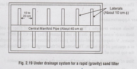
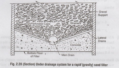
The under drainage system consists of manifold and laterals. The manifold is a 40cm diameter pipe running lengthwise at the centre of the floor bottom. Laterals are 10 cm dia pipes that take off from the manifold in both direction at right angles at 15 to 30 cm spacing. There are two types of manifold and lateral systems:
(i) Perforated pipe type: In this, the lateral drains are provided with holes at bottom side.
(ii) Pipe and Strainer type: In this, strainess are placed on laterals. A strainer is a small brass pipe closed at its top by a perforated cap.
The following rules are followed in the design of under drainage system :
a) The total cross-sectional area of perforations = 0.2 percent of total filter area.
(b) The cross-sectional area of each lateral = 2 to 4 times total cross-sectional
(c) The cross-sectional area of the manifold = twice the cross-sectional area of the lateral drains.
5. Other Appurtenances
(i) Wash water troughs: They are provided at the top of filter to collect the backwash water and to drain it into gutters. They are CI or RCC troughs of square, V-shaped or semi-circular provided across the width or length of tank at a spacing of 1.5 to 2m. The bottom of the trough is kept atleast 5cm above the top level of sand.
Size of the trough can be found by using the following expression:
Q = 1.376 by3/2
where,
Q = total water received by the trough, in m3/s
b = width of trough, in m
y = depth of water at the upper end of trough, in m.
(ii) Air compressors: They supply air for the agitation of sand grains during backwashing. The wash air storage tank should hold atleast double the capacity of air required to wash one filter. The compressed air is supplied at the rate 0.6 to 0.8 cubic metre per minute per m2 of filter area for 5 minutes.
(iii) Rate control device: Flow of influent, effluent, wash water supply and wash water waste must be controlled. A constant rate of filtration is maintained irrespective of the head loss by using rate controllers (venturi type). Otherwise sudden change in the rate of filtration could damage the sand filter bed.
Working and washing of Rapid Sand Filters :
The working of rapid sand filter is controlled by 6 valves:
Valve A : Inlet/ Influent valve through which water from coagulation- clarification basin enters the filter unit.
Valve B: Filtered water storage tank valve.
Valve C: Waste water valve to drain water from main drain.
Valve D: Waste water valve to drain water from inlet chambers
alve E: Wash water storage tank valve
(i) During Normal Working condition:
All valves are closed except A and B, which are kept opened.
Valve A: To permit water from coagulation-sedimenation basin to inlet chamber.
Valve B: To carry filtered water to filtered water storage tank. 2 m head of water is maintained above the sand bed.
Filtration rate is 3000 to 6000 litres/hr/m2 of filter area
(ii) During Backwashing :
The Loss of head initially in a clean filter bed is usually 15 to 30 cm.
As filtration continues, impurities are trapped in the filter media and it provides greater resistance to the flow of water, due to which the head loss goes on increasing.
The permissible head loss in rapid sand filter is 2.5 to 3.5m.
When head loss increases beyond permissible value, the filter bed requires cleaning, which is done between 2 to 4 days interval.
During backwashing, high velocity air and water is made to flow upwards either in combination or first compressed air followed by wash water.
The following sequence of operations is followed :
Close influent Valve A - Allow the filter to operate till the water level falls to the edge of troughs or 15 cm from top of sand.
Close effluent valve B. Open air valve F - Air is blown at a rate of 1 to 1.5 m3 of air/min/ m2 of filter area for 2 to 3 minutes which loosens the scum/ dirt.
Close air valve F.
Open wash water valve E - and waste water valve D-Wash water jets flow upwards (and the waste water from backwashing is drained into
Cleaning is continued till the wash appears clear.
Close wash water valve E. Close waste water valve D.
Allow the solids to settle and form sticky layer on filter media.
Open valve C leading filtered water to wash water drain for few minutes.
Close valve C.
Open valve B - Normal filtration operation is continued.
• The permissible filter bed expansion during backwashing is 25 to 50% of its depth.
• Rate of application of wash water is 600 litres per sq. m. of filter area.
The rapid sand filters get clogged very frequently and have to be washed every 24 to 48 hours. Normally 10 to 30 minutes is required for backwashing.
DESIGN OF RAPID SAND FILTERS
Problem 2.4:
Design a set of rapid gravity filters for treating water required for a population of 50,000; the rate of supply being 180 litres per day per person. The filters are rated to work 5000 litres per hour per sq.m. Assume whatever data are necessary.
Solution:

Hence, two units of size 10 m x 6.75 m are provided with one additional unit as stand-by.
Problem 2.5:
Design a rapid sand filter for 4 MLD of supply with all its principal components.
Solution:
Water required per day = 4 million litres
Assuming 4% of filtered water is used for backwashing
Total filtered water required per day
= 1.04 x 4 ML = 4.16 MLD
Assuming 0.5 hr (30 min) is lost in backwashing everyday
Filtered water required per hour = 4.16/23.5ML/hr (operation time is 23.5 hours)
= 0.177 ML/hr
Assuming rate of filtration = 5000 l/hr/sq.m.
0.177×10⁶
Area of filter required = 0.177 x 10⁶/5000
1/hr / 1/hr/m2 = 35.4m2
Sbie Todtio no almstel 28
Assuming that 2 units are provided
Area of each unit =35.4./ 17.7m2
Assuming = L/B =1.5
Area = L x B = 17.7 m2
(1.5B)B = 17.7
B = 3.43 m/L = 1.5 x 3.43 = 5.14m
Hence, adopt 2 filter units with dimensions
5.2 m x 3.4m
Design of under-drainage system (Manifold and Lateral system)
Total area of perforations = 0.2% of total filter area
(assuming 13 mm dia)
= 0.2 /100 x (5.2×3.4)
= 0.035 m2
Total area of laterals = 2 x total area of perforations
= 2 x 0.035 = 0.070 m2
Area of manifold = 2 x area of laterals
= 2 x 0.07 = 0.14 m2
Diameter of manifold (circular pipe) π/4 I d2 = 0.14 m2
Use 45 cm dia manifold pipe laid lengthwise along the centre of filter bottom. Laterals are laid perpendicular to manifold width-wise at spacing of 15 cm.


No comments:
Post a Comment