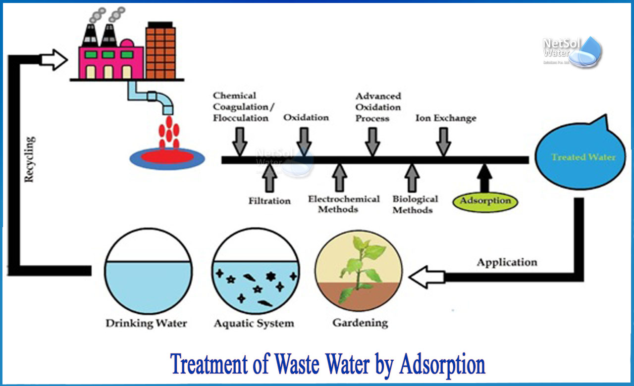
PIPE FITTINGS
Requirements of jointing material
(i) Imperviousness
(ii) Elasticity
(iii) Strength
(iv) Durability
(v) Adhesiveness
(vi) Workability
(vii) Economy
(viii) Availability
Different types of joints are:
(i) Spigot and socket joint
(ii) Flanged joint
(iii) Mechanical joint or Dresser coupling
(iv) Flexible joint
(v) Expansion joint
(vi) Simplex joint
(i) Spigot and Socket joint
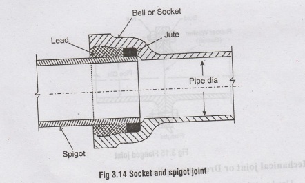
• Used in Cast Iron pipes
• The C.I Pipes are made with one end normal and other end enlarged.
• Normal end is called the spigot end.
• Socket accommodates the spigot end
• The spigot is fitted into the socket
• Jute or yarn is packed into the joint
• The hemp or sterilised yarn maintains alignment.
• Molten lead heated at 400°C is poured and caulked into the joint
• This joint is flexible but requires skilled labour.
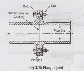
(ii) Flanged joint
• Used in CI pipes cast with flanges at both ends.
• Used in pumping stations and filter plants where disjointing of pipe may required occasionally.
• Two flanges are joined with rubber washer (gasket) and fixed by nuts or bol
• The joints are strong but rigid.
• Expensive
• Cannot withstand vibrations.
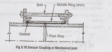
(iii) Mechanical joint or Dresser coupling
• Used to join the plain ends of CI pipes
• A metallic collar is fitted and tightened over the pipe ends, to form Mechanic Joint.
• An Iron ring and gasket are slipped over the pipe ends and an iron sleeve is bemor inserted between the gasket. The iron rings are tightened by bolts to form dresser coupling.
• They are strong and rigid joints
• They can withstand vibrations, useful for pipes over or below bridges.
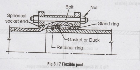
(iv) Flexible joint
• Used where greater flexibility is required.
• Used when pipes are laid in rivers with uneven beds, where large scale settlements may break ordinary joints.
• Used while laying pipes on curves.
• The CI pipes are casted such that the socket is spherical and spigot has bead at the end.
• A retainer ring is placed over bead which keeps gasket in position.
• A split cast iron gland ring is then placed and tightened by bolts and nuts.
(v) Expansion joint
• They are provided at suitable intervals in the pipe lines, to counteract the thermal stresses due to temperature variations. (expansion and contractions).
• The cast iron pipes are casted such that the socket end is flanged and spigot end is plain. YouT
• The socket end is connected rigidly to an annular ring which can slide freely over the spigot end.
• A small space is left between the spigot and socket, which is filled by a rubber gasket.
• Flanges are tightened by nuts and bolts.
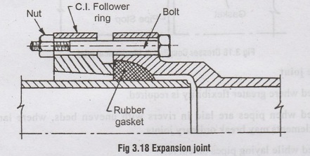
• During expansion, the socket moves forward and the
• During contraction, the socket moves backward and creates gap.
• The annular ring follows the movement of socket
• The Gasket always remains in position and maintans water tightness
(vi) Simplex joints
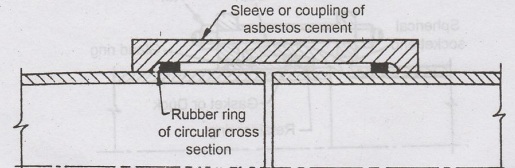
Fig. 3.19 Simplex joint for Asbestos cement pipes.
• Used in asbestos cement pipes.
• A sleeve is fitted over the plain ends of pipes.
• Two rubber rings are compressed between the sleeve and pipe barrels.
• The joints are both flexible and water tight.
Appurtenances in Distribution System
The following appurtenances are required for the efficient functioning of the distribution network.
1. Valves
2. Fire hydrants
3. Water Meters
4. Water Taps
5. Stop Cocks
6. Pipe Bends etc.
1. Valves
(i) Sluice valves (or) Gate valves
(ii) Check valves
(iii) Air valves
(iv) Drain or scour valves
PIPE APPURTENANCES
Appurtenances in water distribution system.
(i) Sluice valve (or) Gate valves
(ii) Air valves
(iii) Scour valves
(iv) Relief valves
(v) Reflux valves
(vi) Altitude valves
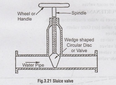
(i) Sluice valve or gate valve
• Used to regulate the flow of water through pipes.
• Useful for carrying out repair works in pipelines.
• They are known as Shutt off or Stop valves to shut off the supply in water line, whenever required.
• Provided at 150 to 300 m spacing and on street corners, intersection of pipelines. low cost and offer no resistance to flow. Placed at summits.
• Mode of cast iron with brass bronze, stainless steel mounting.
• Type (i) Solid-wedge type, (ii) double-disk type
• The valves are joined to pipe ends by standard joints.
• The valve has a wedge shaped circular disc connected to a wheel (handle) by threaded spindle.
• The Valve is raised or lowered by rotating the wheel-manually or mechanically. .
• Head loss through the valve increases when size of valve is less.
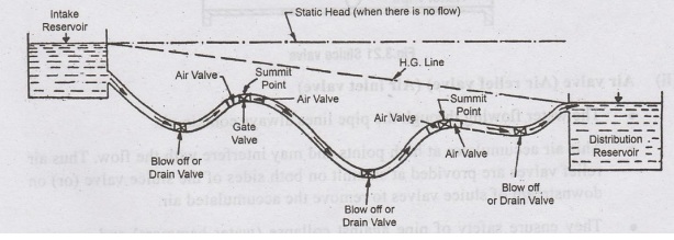
(ii) Air valve (Air relief valve) (Air inlet valve)
• The water flowing through the pipe lines always contain air.
• This air accumulates at high points and may interfere with the flow. Thus air relief valves are provided at summit on both sides of the sluice valve (or) on downstream of sluice valves to remove the accumulated air.
• Air inlet Valves on the other hand, admits air into the pipe when the pipe is emptied.
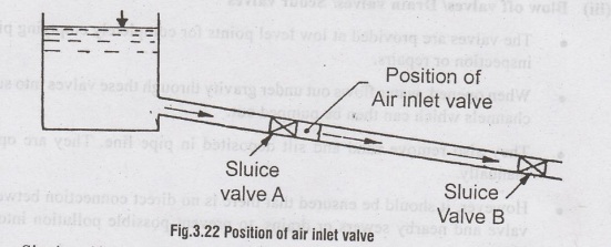
• Single orifice air valve is the commonly used air valve which acts both as an air-inlet valve as well as an air-relief valve.
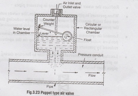
• It consists of a cast iron chamber (circular/ rectangular), a lever and a poppet floating valve. The chamber is fitted to the pipe top. When chamber is filled with water under pressure, the float touches the roof of chamber and valve closes. But, when air accummulates at top and pressure builds up, the water level gets depressed, the float sinks and valve opens. The air escapes out and the process is repeated.
• These valves also act as air-inlet valves. When the pressure decreases to negative, the float drops and valve opened admitting air in pipe to counterbalance the negative pressure.
• The poppet valves are automatic and can function both ways.
(iii) Blow off valves/ Drain valves/ Scour valves
• The valves are provided at low level points for completely emptying pipe for inspection or repairs.
• When opened, water flows out under gravity through these valves into sump or channels which can then be pumped out.
• They also remove sand and silt deposited in pipe line. They are operated manually.
• However, it should be ensured that there is no direct connection between the valve and nearby sewers or drains, to prevent possible pollution into water pipes.
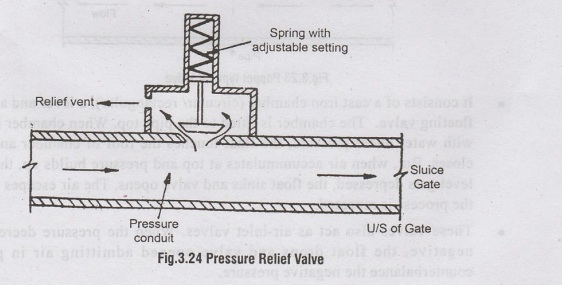
(iv) Pressure relief valves (Safety valve) (Cut off valves)
• Reduces the water hammer pressure in pressure pipes
• When pressure in pipes exceeds a certain value, the valves automatically opens out and small quantity of water flows out of pipe reducing the pressure. When the pressure drops to the desired valve, the valve automatically closes.
• Located on upstream of sluice valves. Due to the sudden closure of sluice valves, positive water hammer pressure may develop on the upstream side, which is reduced by pressure relief valves.
• Located at suitable intervals in water line to function during emergencies due to pressure rise beyond design valve and help in protecting pipe joints and pipes from bursting.
(v) Check valves or Reflux valves (Non-return valves)
• It is an automatic device installed on the delivery side of pumping unit.
• The valve prevents back flow of water when pump is stopped, thereby preventing damage to the pump.
• Check valves, ensure that water flows in one direction only. Signs
• Check valves also reduce the water hammer pressure on the pump.
• The valve consists of a flat disc fixed within the pipeline such that, it is forced open when flow is in one direction and forced shut when flow tries to reverse.
(vi) Altitude Valves
• Used in lines that supply water to elevated tanks or stand pipes.
• They close automatically when the tank is full.
• They automatically open when pressure on the pump side is less than on the tank side of the valve.
(vii) Manholes
• Provided at suitable intervals along the water line for Inspection and Repairs.
• Provided at 300 to 600m spacing in Steel, Hume steel and RCC pipes.
(viii) Insulation Joints
• Provided at suitable intetvals along the pipe line to insulate the pipe against flow of stray currents.
• Rubber gaskets or rings (insulators) are provided in the pipelines to resist the flow of current.
(ix) Anchorages
• At bends, due to unbalanced pressures, the pipes may move out of alignment and the joints gets loosened causing leakage and pipe failure.
• Similarly, the pipes laid at steep slopes tend to slip away. In such cases, the pipes are embedded or anchored in massive blocks of concrete or masonry to absorb the side-thrusts.
2. Fire hydrants
• A fire hydrant is an outlet provided in a distribution main or sub main (i.e. pipe of 15 cm Φ) for tapping water during fire and sometimes used for filling the municipal water tankers.
• They are provided at street crossings or turnings at 90 to 120m interval.
• During fire outbreaks, the fire hydrant is connected to a fire hose or fire engine ydaior to discharge large quantity of water at high pressure.
• Such high pressures are developed by attaching the fire hydrant to the fire engine.
• The fire engine boosts the water pressure within the engine.
• The high pressure water is then discharged out through the hose pipe attached to the outlet of fire engine.
• The pressure developed is atleast 32 m water head.
Water Pressures at the fire hydrants should be:
(i) Using Motor pumps - 7 to 14 m head of water
(ii) Direct flow from fire hydrant - 35 to 50 m head of water
Requirements of good hydrant are:
• Easy to connect hose or motor pump
• Cheap
• Easily detectable during fire
• Provide undisturbed water flow
• Not get out of order during operation.
Types of fire hydrants:
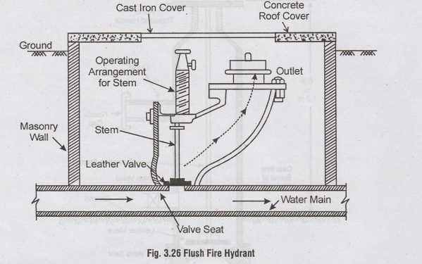
(i) Flush fire hydrant
Installed underground in brick or CI chamber with top cover above the street level. They are less prone to damage. But they are not easily detectable during Inomingil fire. This type of hydrant is widely used in India.
(ii) Post fire hydrant
Its like post standing 0.9 to 1.2 m above ground and can be easily detected but ais liable to damage.
• It consists of a barrel of cast iron, connected to water mains.
• A valve stem; with leather valve at lower end and handle on upper end is provided; to regulate the flow. When closed; leather valve rests against the valve seat.
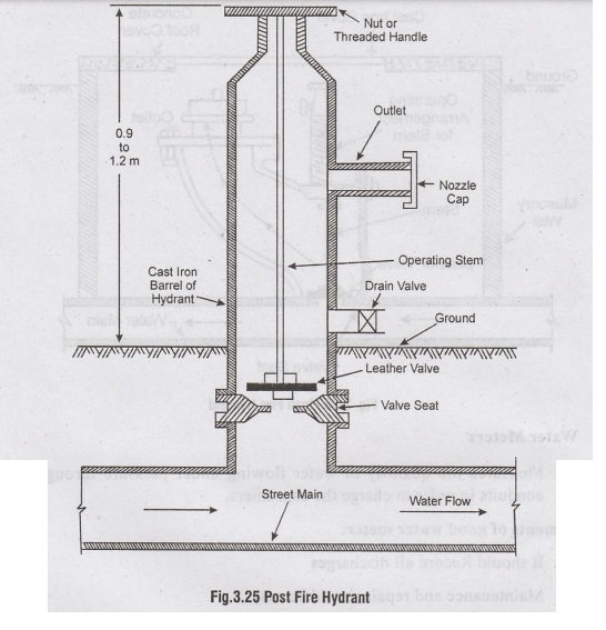
• For opening the hydrant, the Nut/ handle is rotated so as to raise leather valve thereby allowing water inside the barrel.
• Based on the number of outlet openings,. they are classified as one-way, two- way, three-way or four-way hydrants.
• Usually 2 outlets are provided. One connected to hose; when pressure boosting is not required. Other connected to fire engine or pumps; when boosting is required.
3. Water Meters
Measures the quantity of water flowing under pressure through pressure conduits in order to charge the consumers.
Requirements of good water meter:
• It should Record all discharges
• Maintenance and repair should be easy
• Minimum error in measuring discharges (less than 20%)
• Work efficiently at all pressures
• Minimum hindrance to flow (Min. head loss)
• Parts should not be damaged by chemicals present in water
• 200Prevent backflow and should not be liable to clogging.
Types:
(i) Velocity/Inferential Meters
(ii) Positive/Displacement Meters
(i) Velocity / Inferential meters
• It measures horizontal flow velocity (V)
• Discharge through the meter is computed by
Q=Ax V
Where, A = Area of flow cross-section
• Automatic arrangements are made to record the discharge directly over a period of time
• They can measure high flows
• Widely used in Industries / Trade
• They can be used for measuring raw and sedimented water.
• They are not used for small domestic supplies, as their occuracy is less during low flows.
Types of Velocity Meters:
a) Rotary meters
b) Turbine meters
c) Venturi meters
a) Rotary meter
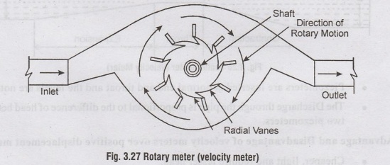
• Consists of radial vanes attached to a shaft, enclosed in a casing.
• When water passes through the meter, radial vanes are rotated in clockwise direction, which revolve the shaft.
• The number of revolutions per unit time depends on flow velocity.
• The velocity of flow and discharge is proportional to speed of shaft.
• The meter is calibrated to directly read the discharge or the total discharge over a period of time.
b Turbine meter
• Similar to rotary meter
• Consists of a rotary turbine wheel which is rotated by moving water.
• The number of revolutions made by turbine wheel gives the discharge.
c) Venturi meter
• Follows the Bernoulli's principle.
• Used for raw water and measuring high flows in large pipes with minimum head loss. It is not suitable for low flows.
• It consists of a gradually contracting pipe with a throat section and a expanding pipe section.
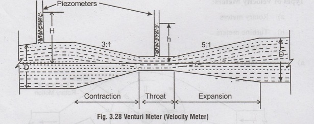
• Piezometers are inserted at normal end and throat and the levels are noted.
• The Discharge through the pipe is proportional to the difference of head between two piezometers.
Advantage and Disadvantage of velocity meters over positive displacement meters:
• Cheaper, light and require lesser head.
• Less accurate
• Installed only on horizontal pipes.
(ii) Positive or displacement meters
• More accurate and they measure the quantity of passing water by counting the number of times the meter chamber is filled and emptied.
• Quantity of flow over a given period of time = Capacity of meter chamber x number of times of filling and emptying.
Types:
(i) Reciprocating type
(ii) Oscillating type
(iii) Disc type (common)
• The Disc type meter consists of a disc placed inside a chamber provided with inlet and outlet.
• When water enters the chamber, the disc oscillates with a spiral motion.
• One revolution means one complete filling and emptying of chamber.
• The discharge is recorded automatically by the revolution of gears.
• This meter is widely used for measuring small flows in residential houses. 3.6