CLARIFIERS FOR WASTEWATER TREATMENT
Clarifiers are settling tanks built with mechanical means for continuous removal of solids being deposited by sedimentation. Clarification is the oldest and most widely used operation in the effective treatment of wastewater. A clarifier is generally used to remove solid particulates or suspended solids from liquid for clarification and (or) thickening by gravitational settling. These are classified into primary and secondary. This also used grits and solids removal, removal of oil and grease.
A primary wastewater treatment system includes two types of equipments, primary clarification and physical – chemical treatment unit depending upon the components.The main purpose of a clarifier system is to produce a cleaner effluents and to remove solids.Mechanical Clarifiers in the activated sludge process serve a dual purpose. They must provide a clarified effluent and a concentrated source of return sludge for maintaining process control, removing sediment, turbidity, and floating material from wastewater.
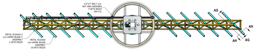 A Clarifier Mechanism Assembly
Clarifiers Basic Principle:
Clarifiers are slowly rotating rake arms, A liquid feed with suspended solids is fed to the clarifier tank.Clear Liquid overflows the top of the tank and is collected in a trough.Bridge support, column support and traction are the three main types of clarifiers, Primary and Secondary clarifiers.
The primary clarifier slows the water down and removes the solids that settle on the bottom with a rotating sludge raking system. It also removes solids that float to the surface of the tank with its rotating rake skimming system. Thereafter, the wastewater is slowly removed from the tank and delivered to oxidation ponds for the next step in the process. The smaller clarifiers are used when incoming wastewater volume exceeds the capacity of the larger clarifier or during maintenance of the larger clarifier.
Clarifiers Vs Thickeners:
Thickeners as well as clarifiers are both used to separate liquids and solids by settling process with only one difference i.e. thickeners concentrate solids whereas clarifiers used to only purify liquids. clarifiers are both circular or parallel plate.The Bridge support clarifiers are used as primary wastewater treatment. The large objects will be screened out of the water, raw water is fed into the primary clarifier. Traction units also have a center column, but the drive power is supplied by a trolley that rides along a track at the tank wall.
Most of the clarifiers are equipped with flocculator / flocculation zone to ensure proper dosing of the chemicals. Clarifiers are available in self-supporting prefabricated steel units or they can be designed for installation in a concrete tank. Existing structures and systems can sometimes be utilized and upgraded for cost savings.
Circular Clarifiers normally utilize a center feed inlet well or a peripheral inlet. The center feed well design can be equipped with a chemical addition system with mixing and flocculation. With the center feed well, the effluent is discharged along the outer wall of the clarifier tank. Clarifiers with peripheral inlets will be designed with a center bottom liquid outlet.
Clarifiers work on the principle of gravity settling. The heavier suspended solids settle in the clarifier and are swept to the center for collection of sludge. Continuous Addition of coagulants and poly electrolyte are used for natural settling. The coagulant neutralizes the charge and poly electrolyte brings together the micro flocks turning them into heavy flock which settles down easily.
Characteristics of a ClarifiersIt can be installed by modifying the existing facilities (primary sedimentation tank, rainwater sedimentation tank).
Because natural down flow is used both for treatment process and washing process, stable operation depending on flow rate fluctuation is possible.
Because the filter media is very fine, a non-flocculation process is available. Because of this, the maintenance and management cost is needed only for electricity, which is as low as 0.1 yen/m3 (excluding pumping cost) without the need for working in rainy weather.
Neither a pre treatment screen nor bottom screen for preventing flowing out of filter media are needed, which makes the operation management easier.
Because the number of in-tank devices and auxiliary devices is fewer, operation management is easier.
Because the time for washing filter media is short (1 min.), no auxiliary tank is necessary.
Efficient elimination of SS makes it possible to reduce the dose of disinfectant in filtrated water by 40% compared to the water after simplified treatment in the conventional approach.
How does a clarifier work?
The clarifier uses a parallel plate design. Water is fed into the inlet trough of the flocculation tank. The wastewater and polymer flocculant are introduced simultaneously in the flocculation mixing chamber, if that option is selected. The flocculated water then flows over the first baffle, then under the second and finally flows to the body of the clarifier. The overflow/underflow allows time for the solids to gain size so that they settle out more easily. The wastewater is then directed to the bottom of the cone and back up through the plate pack. Some solids will settle as the waste stream makes its way to the clarifier cone. However, some particulate will be pushed up to the plate packs. The 60 degree angle of the plates provides a highly effective settling area in a small footprint. As some solids are forced up to the plate pack they start to settle upon each other gradually becoming heavier and ultimately slide down the plate pack to the clarifier cone. The clean water overflows from the effluent port and is suitable to proceed to the drain to city sewer or to an inspection tank. Sometimes a portion or all can be polished and reused. The clarifier sludge is then pumped from the bottom of the clarifier into a sludge thickening tank to feed a Met-Chem filter press.
Can I pump the sludge from my clarifier directly into my filter press?
It is not optimal to pump sludge from a clarifier directly into a filter press. In order to optimize efficiency of the filter press, it is better to let the sludge thicken further in a sludge holding tank and feed the filter press with high sludge content. The sludge thickening tank will also act as a buffer; receiving sludge when the clarifier is ready to dump the sludge, and feeding the filter press as it is ready to receive the sludge. The clarifier and the filter press may not always be ready to work at the same time and the sludge holding tank can be used to accumulate the sludge.
What type of routine maintenance is needed for a clarifier?
Maintenance for a clarifier is minimal. There are few moving parts, if any. Metering pumps for flocculation as well as the mixer should be inspected and maintained according to the OEM guidelines. The clarifier itself will only require and occasional clean out by draining the unit and hosing off any residual sludge at the plate packs and in the cone(s). If the sludge is pumped out regularly, as needed, without allowing the sludge of override the plate pack, this will seldom be required.
What is the purpose of a sludge blow-down system?
The cone of the clarifier will collect the sludge that is settled out of the waste stream. This sludge accumulates at a predicable rate of clarifier use. Rather than relying on an operator to be available at the required sludge draining intervals, once established for your application, the Sludge Blow-Down System will time the duration of the clarifier cycle and automatically open the drain valve in the cone of the clarifier and turn on the sludge pump to remove the accumulated sludge. Another timer will time this operation and automatically stop the process and reset the main timer and start over again. Once the operator establishes the cycle times for these operations, the Sludge Blow-Down System repeats automatically, freeing the operator for other tasks. The Sludge Blow-Down System will also know if the waste stream flow has stopped and will resume timing once the flow restarts.
Will a clarifier remove grease and oil?
It is best to remove oil and grease before sending a waste stream to the clarifier. The Met-Chem clarifier is equipped with an outlet skimmer that will hold captive a small amount of free oil, but this is only a safety net for a small amount of oil the was not properly removed. The operator will need to skim off any oil that is captured by this skimmer.
Can I install my clarifier on my own?
The Austro Water Tech’s clarifier is simple and easy to understand and to install. It is very common for the end user to install the unit, and Austro Water Tech will always be available for phone or e-mail consultation. The unit only requires to be level, and to have enough head feed from the previous tank to gravity flow in and out. If your schedule will not allow you to install, or you do not have the rigging equipment, Austro Water Tech’scan quote a Turn-Key installation complete with training for your team. We are also happy to quote a working supervisor to guide and train your team during the installation.
What happens if my wastewater flow rate exceeds the maximum flow rate capacity of my clarifier?
It is always best to oversize the clarifier. For example, a 60 GPM clarifier can operate very efficiently at 30 GPM or even less. However, a flow rate grater then the rated flow can cause unwanted turbulence and upset the settling of the clarifier. The sludge is likely to get caught in the higher flow and get pushed past the plate pack and out to city sewer. Retention time and surface area to flow rate ratio will be reduced and the clarifier will be unable to stay in compliance.
What is rat-holing and how can I prevent it?
The sludge pump cannot pump sludge faster than the sludge can sink in the cone. If the pump pulls out the sludge too fast, it will suck through the sludge and access clean water. Just like sucking air through a straw while drinking a thick milkshake, the pump will bypass the sludge and pump out clean water while the sludge remains. The sludge pump must pump slowly to avoid Rat-Holing.
Do I need to replace the plate pack on my clarifier?
Normally the plate pack will only be damaged when someone attempts to walk on the plate pack and physically breaks it. Over time and depending on the chemistry involved, it may become brittle, but should not break unless abused.
What is retention time and hydraulic loading?
The two most important aspects of any clarifier are; retention time and the surface area (hydraulic loading). Retention time is the time required for a drop of water to flow from the inlet to the outlet. The greater the retention time, the longer the water will stay in the clarifier (the slower the flow rate) and the more time the solids will have to settle out. A proper minimum retention time will be 50-60 minutes.Hydraulic loading is the relationship between the effective surface area to the flow rate. A typical Met-Chem hydraulic load would be 0.2 GPM of flow to every square foot of surface area offered in the plate pack.
What are the factors that affect clarifier operation?
Various factors affect clarifier efficiency, such as the type of solids in wastewater and where they come from, how long it takes to travel through the system, hydraulic detention time, the design of the tank and the condition of the equipment as well as the temperature of wastewater.
Difference Between Primary and Secondary Clarifier:
The best way to assess the operational performance of a primary clarifier is to review the treatment efficiency for suspended solids removal. If the clarifier shows erratic or inconsistent results, look for hydraulic loading increases (calculated as gallons per day per square foot; m3/day/m2). If the efficiency of removal for suspended solids does not average 40-50%, or BOD averages of 20-30%, over an extended period of time, look for turbulence in the basin or other operational deficiencies.
A secondary clarifier is meant to not only settle the solids and allow clear water to flow over the weirs, but it is also meant to be a thickener. It’s purpose is to thicken the biological solids for two reasons. To be able to return some of the solids back to the aerated portion of the system for more BOD degradation, but to also thicken the solids so that dewatering is easier.
By thinking of the clarifier as an extension of the Aeration Basin, where continued biological degradation and final polishing of the water and bacterial floc occurs, the system can be optimized easier. Polymer usage in a secondary clarifier can be cut back significantly or eliminated with the right optimization.
Austro Water Tech Provides custom Engineered Clarifiers to Your Needs, We provide Full and Half Bridge Designs with an availability of Chemical Feed System, Steel or Concrete Tanks for Proper Sludge Removal along with resistance to Corrosion.
Working Video
Throughout history, sedimentation has served as a tried and true method for wastewater treatment. Gravity forces contaminants to settle downward in the surrounding liquid whereas clarified water can be removed separately. The same principle is used by wastewater treatment clarifiers: Large tanks provide enough retention time to slow water down and to separate out suspended particles.
Wastewater from aeration basins is usually entering the clarifier from a centrally located pipe. The entering wastewater is also known as the MLSS (mixed liquor suspended solids) which refers to the concentration of suspended solids from the activated sludge process. To slow down the incoming water its directed through a energy dissipating inlet and a feedwell.
Inside the clarifier solid contaminants will settle down to the bottom of the tank where it is collected by a scraper mechanism and removed by another centrally located pipe. The scraper mechanism arms rotate slowly along the clarifiers perimeter and are attached to a centrally located shaft which is powered by a drive system on the clarifier bridge. The removed sludge will either by recycled as RAS (return activated sludge) or wasted as WAS (waste activated sludge). The clarified water instead is released over overflow weirs on the top of the clarifier. In properly functioning clarifiers the overflow water looks already very clear. Fats, oil, grease and other floating substances are removed by a rotating skimmer on the water surface.
In some tanks, called tube settler or lamella clarifier tanks, there are additional inclined plates or channels inside the tank to help force solids to settle out of the mixture.
In many cases, flocculants or coagulants are applied to the wastewater before it reaches the clarification tank to make the sedimentation process more effective. The chemicals are usually added in mixing tanks with agitators, which provide a gentle stirring for even distribution of chemicals in the water.
One model for proper operation and evaluation of a clarifier is called the state point analysis. The SPA can be visualized in a diagram showing the balance between a solid concentration on the X-axis and the solid flux rate on the Y-axis. The solid flux rate describes the mass of solids passing through the clarifier in one hour and per m2 of clarifier surface. The diagram includes three curves: The settling curve of the particles, the overflow curve to represent the flow through the clarifier and the underflow curve to represent the RAS rate in the clarifier. The goal is to have the intersection of the overflow and underflow curve underneath the settling curve to allow enough time for solid settling. Furthermore, the complete underflow curve must stay underneath the settling curve to allow enough time for sludge thickening and removal.
Clarifier efficiencies are affected by many factors, including:
The nature of solids in the wastewater and their source. A large industrial contribution to a municipal wastewater plant will have solids with very different characteristics compared to the solids from a “conventional” municipal plant.
The transit time and temperature of the wastewater stream will have a large, negative impact on the solids. Higher wastewater temperatures and long transit times increase the likelihood of the wastewater becoming septic. Septic wastewater reduces the settling rate of solids due to gas bubble attachment, increasing the buoyancy of the solids, keeping them in suspension.
Hydraulic loading rate on the clarifier. Higher loading rates will reduce solids settling.
Maintenance status of the clarifier. Performance differences between well-maintained and poorly-maintained clarifiers can be significant.
Recycle streams, such as waste activated sludge, digester supernatant, dewatering centrate/filtrate streams, will have a negative impact on the settling of solids. In addition, as solids are recycled around a treatment plant, the particle size continues to reduce, increasing surface area, slowing the rate at which the small particles will settle.
Detention time in the clarifier needs to be in the range of 2.0 to 3.0 hours. Too short a detention time will cause solids carryover and too long a detention time will increase septicity. In my experience 3 hours of detention is too much and will likely increase septicity in the sludge during warmer months. Different sources will show different values for all of the operating parameters shown in the table below.
Temperature can also be a factor during winter when the wastewater temperature drops and long detention times in the clarifier add to the cooling. As the temperature drops the density of the wastewater will increase, slowly the rate at which solids will settle.
In the primary clarifier graphic below you will note the detention time is shown as 1 to 2 hours. BOD and TSS removal rates are also shown for the "conventional" operation of a primary clarifiers in contrast to the increased removal rates for chemically enhanced primary treatment (CEPT) where the addition of chemicals, such as a metal salt like ferric chloride followed by an anionic polymer, are used to improve the operation of the clarifier.
Primary Clarifier Formulas
Detention Time when the volume of the tank, in gallons, is known.
Detention Time when the volume of the tank, in cubic feet, needs to be calculated from the clarifier dimension.
Where the volume of a circular clarifier is calculated as follows:

And the volume of a rectangular clarifier is calculated as:

Weir Overflow Rate
The weir overflow rate (WOR) parameter is used to determine both the potential for short-circuiting in the clarifier and excessive velocities over the weir which would increase the quantity of solids carried out of the clarifier. The weir overflow rate is the number of gallons of wastewater that flow over one lineal foot of weir per day. The typical WOR range for primary clarifiers is 10,000 to 20,000 gallons per day per lineal foot of weir.
Where GPD represents gallons per day.
Surface Settling Rate or Surface Loading Rate
The recommended surface loading rate for primary clarifiers is 300 to 1,200 gallons per day (GPD)/square foot. Loading rates are sometimes varied in response to wastewater temperature, being decreased, by putting more clarifiers in service, during the colder season. During summertime conditions, when the wastewater temperature is elevated, having fewer clarifiers in service will reduce detention time, reducing the potential for septic sludge, though the solids loading rate increases.
The area and circumference of a circle is calculated as follows:
In case you are wondering, the factor 0.785 used in the equation above for calculating the area the area of a circle using the diameter is derived as follows:
Secondary Clarifiers
Secondary clarifiers handle a large concentration and volume of solids due to the mixed liquor suspended solids (MLSS) leaving the activated sludge process. The typical range for MLSS concentrations in the activated sludge process is between 1,800 and 4,000 mg/L. This range applies fairly well to municipal wastewater plants but often does not nearly match conditions in an industrial wastewater system.
On many occasions I have seen MLSS concentrations exceeding 10,000 mg/L in chemical, petrochemical, and food & beverage wastewater plants. These excessive MLSS concentrations not only place a heavy burden on the secondary clarifiers, which are often loaded with solids floating on the surface, but these extreme concentrations also overload the biological treatment system, reducing oxygen transfer efficiency, and causing an overall low dissolved oxygen (DO) condition throughout the bioreactor. Oxygen in the bioreactor is one of several critical "nutrients" required by bacteria. When the DO is low a stressed condition is created in the bioreactor and BOD/COD reduction suffers.
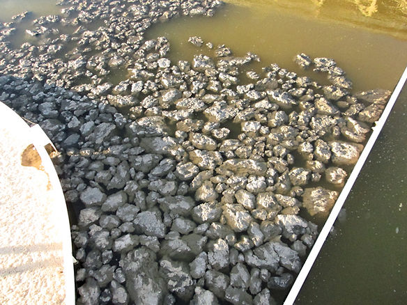
The picture below, of a secondary clarifier, was taken at a food plant which carries an MLSS concentration greater than 14,000 mg/L!! Sadly, this is not an exaggeration.
A lot more analysis goes into the design and evaluation of secondary clarifiers compared to primary clarifiers, where four types of settling are evaluated as follows:
1. Discrete settling, controlled by the overflow rate.
2. Flocculent settling, controlled by the overflow rate and depth of the clarifier.
3. Zone settling, controlled by the solids flux (see the page on State Point Analysis).
4. Compression settling, controlled by the solids retention time and the sludge depth.
What is provided here is a very general review of secondary clarifier operation. If you really want to know more about clarifier design I recommend you purchase the “Clarifier Design” textbook, published by the Water Environment Federation (Manual of Practice No. FD-8). This excellent reference will provide you with all the detailed information you need to truly understand clarifier design.
To Be Noted
What you should note in the table above is that the recommended detention time of 2.0 to 3.0 hours is the same for both primary and secondary clarifiers, as is the surface settling rate. Where this table differs from the primary clarifier table is with the reduction in the weir overflow rate for secondary clarifiers. In addition, a range for the solids loading rate is shown for secondary clarifiers, a parameter typically not used in the design of a new primary clarifier or the evaluation of an existing primary clarifier.
Solids Loading Rate
The solids loading rate (SLR) is the quantity of solids that can be removed by a secondary clarifier per square foot of surface area. An increase above the design SLR will likely result in an increase in solids leaving the clarifier. For secondary clarifiers that follow an activated sludge system the solids loading rate should fall in the range of 12 to 30 pounds of solids per day per square foot of clarifier surface area. Depending on the textbook you reference, you will see a somewhat different range for the SLR.
The formula for calculating the solids loading rate for a secondary clarifier is:
Where the solids applied represents the pounds of mixed liquor suspended solids flowing to the clarifier, calculated as follows:
State Point Analysis
A simple but comprehensive method to evaluate the performance of your secondary clarifiers is the use of State Point Analysis (SPA).
Excel Spreadsheet
If you have read this far in this rather lengthy post you may find you have benefited from being able to download an Excel spreadsheet that assists in determining key wastewater secondary clarifier calculations. This spreadsheet is shown in the screenshot below.
Required inputs to the spreadsheet are:
1. The influent flow rate,
2. The MLSS concentration,
3. The return activated sludge flow rate, and
4. The number of clarifiers in service.
The spreadsheet then calculates the:
1. Surface overflow rate,
2. Weir overflow rate,
3. Solids loading rate, and
4. The detention time, taking into account the appropriate flow rate.


No comments:
Post a Comment