Rotary pumps are those pumps where pumping action of pump displaces a costant amount of fluid per revolution of pump shaft.
ROTARY PUMP
(1) Rotary pumps are those pumps where pumping action of pump displaces a costant amount of fluid per revolution of pump shaft.
(2) Rotary pumps are positve displacement pumps. They are clasified as follows.
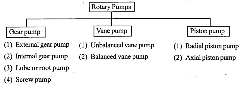
1. Gear pump (External)
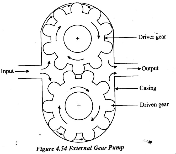
Figure 4.54 shows a typical external gear pump in two gears meshes externally to provide the pump action. It consist of two identical gear one is drive gear and another one is a driven gear and these are enclosed in a precision machined housing (or) casing. The fine clearance between the gear and casing acts as seal between the outlet and inlet side of the pump. In the gear pump the suction side forms where teeth came out of mesh and discharge side formed where teeth started meshily. The liquid is carried from suction side to delivery side on the chambers or pockets formed between teeth and housing. Hence when the gear starts rotating the trapped fluid is transferred to the delivery side. The mechanical contact between the gear does not allow the direct flow of liquid from suction to delivery side. Gear pumps may be noisy in operation and produces excessive and thrust.
2. Internal Gear pump
The internal gear pump with a regular spur gear and internal gear or rotor.
A consent shaped spacer is placed between these gear to form closed assembly and pockets to carry the fluid. The spur gear drives the internal gear. The inlet or suction side is locating near one end of crescent where gears teeth un mesh.
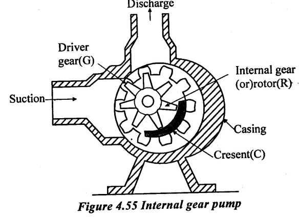
The discharge part is located at the other end of crescent where gear teeth starts meshing again. When the driver gear starts rotating, the fluid tight seal forms where teeth meshes with each other. The rotation of gear causes the unmeshing of teeth near inlet port and cavity volume increases. This produces vacuum at inlet and the fluid to be pumped get sucked inside the pump.
This fluid is carried through the pockets fromed by teeth around the crescent. The fluid is then forced out into the outlet port.
3. Lobe or Root pump
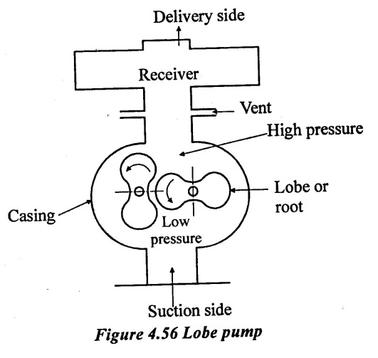
The arrangement of lobe or root type pump is show the Figure 4.56. It consists of two lobes driven externally. One of the lobe is connected to the drive and another lobe is gear driven from the first. The lobe have two or three teeth of epicycloids, hypocycloid or in volute profiles. The high pressure (delivery) side is sealed from the low pressure (suction) side at all angular positions. To prevent wear and tear a small clearance is maintained between the surface. But the leakage through this clearance decreases the efficiency of compressor.
During the rotation of lobe, volume of liquid at atmospheric pressure is trapped between the left hand rotor and casing. This liquid is squeezed between the lobes and high pressure liquid is delivered to the receiver. Three and four lobe versions are also used for higher pressure.
During the process the volume of liquid Vs at atmospheric pressure P1 is entrapped between the rotor and casing. This volume does not decrease from entry of exit and hence the pressure is not developed until the exit port is opened.
When the exit port is opened high pressure liquid from receiver will rush back and mix with the volume V1 irreversibly till the pressure is same.
4. Screw pump
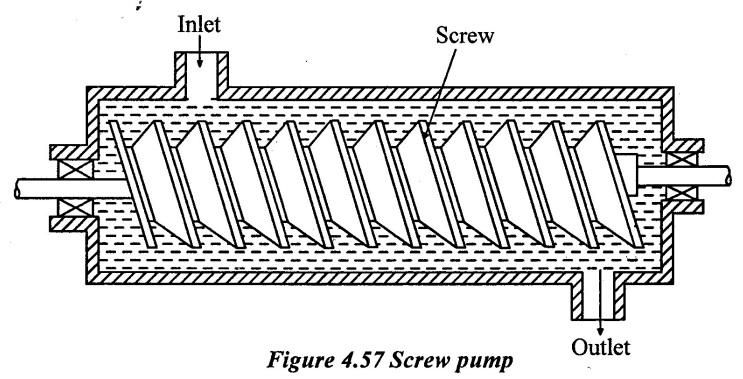
A screw pump is an axial flow positive displacement pump.
It uses several screws meshing with in a close fitting housing to moves fluid or solids along the screw axis shown in figure 4.57.
By rotating screw within a cylindrical cavity the fluid flows along the screw spindle
In a screw pump, three screw meshes with each other one screw acts as a power rotor which transmitted the power other two screw act as idlers. These two idlers and rotors turn because of the action of the fluid transferred through pump. They act as a rotating sealing element. The pumping action occurs when the meshing of rotors seal and un fold the fluid.
Screw pump transfers the fluid uniformly and eliminate the noise and vibration.
5. Vane pump

The arrangement of vane type pump is shown as Figure 4.58.
It consists of eccentrically mounted rotor in the body of the pump. The rotor is slotted to contain the vanes of non-metallic material. The rotor is supported by ball and roller bearing.
As the blade moves past in the inlet passage, the liquid gets entrapped in the passage between two vanes. The liquid now get compressed due to decreasing volume between the rotor vanes and casing. The compressed liquid is delivered when the each vane arrived at the delivery passage.
The complete compression is carried out before the trapped liquid is opened to delivery passage. As compared to rotor pump the vane pump required less work for the same capacity and pressure rise. The major source of leakage is gear and root pump is the gap between teeth and housing. This is eliminated in the vane pump.
Example : 38
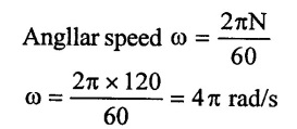
A double acting reciprocating pump runs at 120rpm when its suction pipe of 100mm diameter is fitted with an air vessel on its suction side. The diameter of cylinder and stroke are 150mm and 450 mm respectively. If piston is to be driven with S.H.M, find the rate of flow from or into the air vessel when the crank makes angles of 30°, 90° and 120° with the inner dead centre. Find also the crank angles at whch there is no flow into or from the air vessel.
Given data:
Speed (N) = 120 rpm
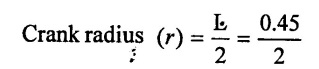
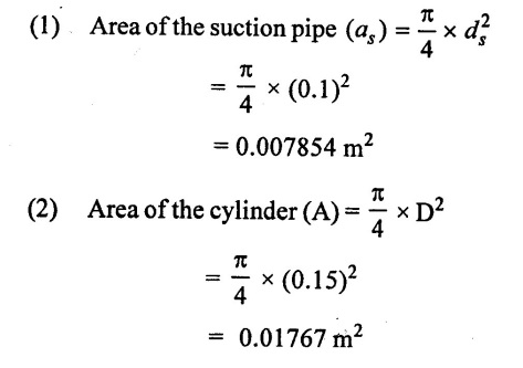
Dia of suction pipe (ds) = 100 mm = 0.1m
Dia of cylinder (D) = 150mm = 0.15m
Stroke length (L) = 450 mm = 0.45 m
= 0.225 m
To find:
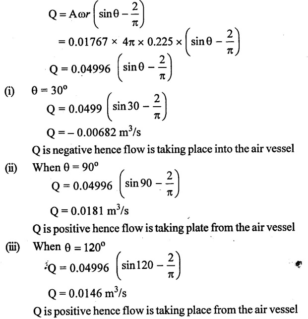
(i) Rate of flow from (or) into the air vessel when θ = 30°, 90°, and 120°
(ii) Crank angles at which there is no flow
Solution:
(3) Rate of flow of liquid into air vessel for double acting pump
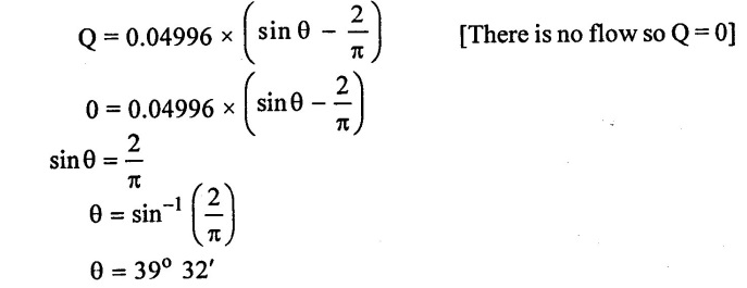
(4) Crank angles at which there is no flow into (or) from air vessel
Result:
(1) Q = -0.00682 m3/s at θ = 30°
(2) Q = 0.0181 m3/s at θ = 90°
(3) Q = 0.01146 m3/s at θ = 120°
(4) Crank angles when there is no flow θ = 39°.32′
No comments:
Post a Comment