The reciprocating pump is a positive displacement pump. It has a piston that executes reciprocating motion in a closely fitting cylinder.
RECIPROCATING PUMPS
The reciprocating pump is a positive displacement pump. It has a piston that executes reciprocating motion in a closely fitting cylinder. The liquid is drawn in and raised by the actual displacement of the piston inside the cylinder. The amount of liquid pumped out is equal to the volume displaced by the piston. The reciprocating pumps with disk piston can developed pressure upto 25 bar while the reciprocating pumps with pistons can develop much higher pressure. The discharge of liquid depends on the speed of the piston. The reciprocating pumps are best suited where we require small discharge at very high head of in oil filling operation.
1. Classification of reciprocating pumps:
(1) According to the action of pump:
(i) Single acting pump:
The working fluid is in contact with one side of the piston that pump is called single acting pump.
(ii) Double acting pump:
The working fluid is in contact with both sides of the piston that pump is called double acting pump.
(2) According to number of cylinders:
(i) Single cylinder pump:
A single cylinder pump may be single acting (or) double acting and delivering water with a single cylinder.
(ii) Double cylinder pump:
A double cylinder pump has two cylinders, each equipped with one suction and one delivery pipe with appropriate valves are with separate pistons get each of the cylinders. Both the pistons are simultaneously driven from cranks set at 180°.
(iii) Triple cylinder pump:
This Pump has three cylinders, each equipped with one suction and one delivery pipe. All the three piston's are simultaneously driven from cranks set at 120°.
(iv) Duplex double acting pump:
Combination of two double acting single cylinder pump of two double acting cylinder pumps. The two cranks are get 90°.
(v) Quintuplex pump:
It has five single acting cylinders driven from a crank set at 72°. In general reciprocating pump having more than one cylinder is known as a multi cylinder pump.
(3) According to the Existence of air Vessels:
(i) With air vessel
(ii) With out air vessel
2. Single Acting Reciprocating Pump
A single acting reciprocating pump consists of the following parts as shown in figure 4.42.
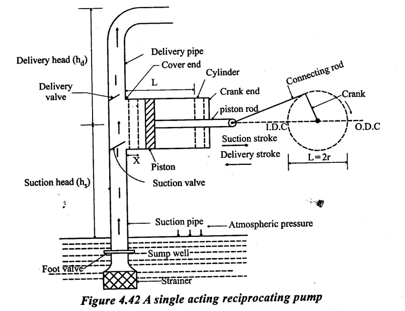
1. Cylinder with piston:
A cylinder in which a piston works. The movement of the piston is obtained by a connecting rod, which connects the piston through piston rod and rotating crank.
2. Suction pipe:
It connects the source of water [sump water] and the cylinder.
3. Delivery pipe:
The water sucks from the sump is discharged by the movement of piston through this pipe suction valve.
4. Suction valve:
It admits the flow from the suction pipe into the cylinder.
5. Delivery valve:
It admits the flow from the cylinder into the delivery pipe.
6. Motion Mechanism:
The motion mechanism consisting of connecting rod, crank and crank shaft driven by some prime mover like as electric motor etc...
Working:
As the electric motor or I.C engine shaft rotates the crank, the piston reciprocates inside the cylinder. During the first stroke of the piston water is drawn into the cylinder, this stroke is called suction stroke. In the second stroke of the piston, the water is delivered from the cylinder, this stroke is called delivery stroke.
Suction Stroke:
As the crank rotates in the clockwise direction by half rotation, the piston moves from the cover end to the crank end. As the piston gradually moves to perform this stroke the volume covered by the piston within the cylinder increases while the pressure decreases below the atmospheric pressure. On the free surface of the water in the sump atmospheric pressure will be acting. There is a pressure difference at the two ends of the suction pipe which connects the sump and inside the cylinder causes the flow of water from the sump into the cylinder through the suction valve which is kept open by the inward flow of the suction water. During this stroke, the non-return valve of the delivery side will be closed due to the atmospheric pressure in the delivery pipe. At the end of this stroke the cylinder will be full of water. Since the water is continuously sucked into the cylinder, this stroke is called suction stroke. At this end of this stroke, the pressure in the cylinder is a atmospheric pressure and the suction valve is closed.
Delivery Stroke:
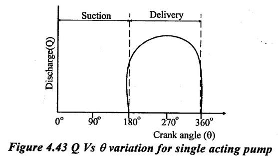
As the crank continues to rotate, the piston performs the return stroke, in which it moves from the crank end to the cover end. As the piston moves in the cylinder, the pressure of water in the cylinder will increase, this in crease in the pressure opens the delivery valve and the water is continuously delivered from the cylinder. Hence this stroke is called delivery stroke. After the completion of the delivery stroke, again the piston is ready to perform the suction stroke of the next cycle. Since the delivery of the water takes place only during the delivery stroke, i.e., only during half of the crank rotation, the discharge is not continuous but intermittent. This reciprocating pump is single acting, because the suction and delivery of water is taking place only on one side of the piston. This type of pump is suitable for high pressure and low discharge.
The variation of discharge (Q) through delivery pipe with crank angle (0) for single acting pumps is shown in figure 4.43. The discharge is given by the pump in a delivery stroke only.
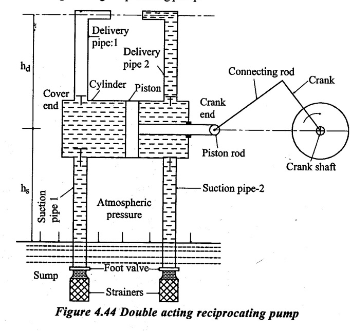
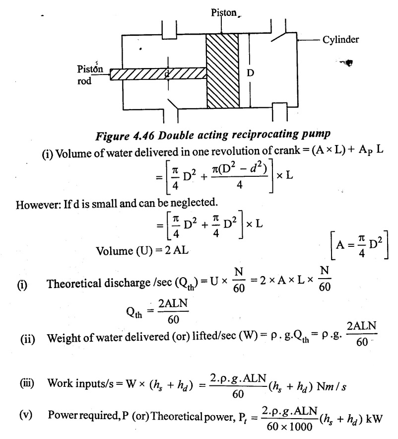
3. Double acting reciprocating pump:
A double acting reciprocating pump shown in figure 4.44 consists of two suction pipes and two delivery pipes being fitted at each end of the cylinder. Other parts are same as that of single acting reciprocating pump.
Working:
When the crank rotates in the clockwise direction by half rotation, the piston moves from the cover end to the crank end. As the piston gradually moves, a vacuum is created on the left side of the piston and the water flows from the sump into the cylinder through the suction pipe -1. At the same time the water on the right side of the piston that was drawn into the cylinder during the previous stroke will be continuously delivered through the delivery pipe -2. Thus during this stroke, the suction of water into the cylinder will be taking place on the left side of the piston, simultaneously on the right side of the piston, the delivery of the water that was drawn during the previous stroke will be taking place and this will continue till the piston moves to the crank end.
In the return stroke of the piston, which take place from the crank end to the cover end, exactly reverse of what was happening in the previous stroke takes place inside the cylinder. That is, a vacuum will be created on the right side of the piston which causes the suction of water through the suction pipe -2 into cylinder with simultaneously delivery of water on the left side of the piston, which was drawn during the previous stroke through the delivery pipe-1.
Thus the water will be discharged during every stroke of the piston. This pump called double acting reciprocating pump because the suction and the delivery will be taking place on the both sides of the piston. Although the discharge is continuous but will not be uniform like in centrifugal pump.
As the crank rotates, vacuum is created to suck water in one side while water is forced out in the delivery pipe in other side of the cylinder. Hence, there is simultaneous delivery and suction strokes taking place resulting more uniform discharge as shown figure 4.45.

4. Advantages of a reciprocating pump:
a) It is self priming.
b) It is used where high head and low discharge are required.
c) It has high efficiency.
d) It can develop much higher heads as required in oil exploration.
5. Disadvantages of a reciprocating pump:
a) It cannot run at high speed.
b) It is has pulsating flow
c) There is non-uniform load torque on the crankshaft.
d) Air vessels are to the provided in the suction and delivery line to smoothen the pump.
e) It needs care in its operation. Delivery valve has to be kept open before starting the pump.
f) It is unsuitable to pump viscous liquids such as paper and sugar molasses etc.
g) It is unsuitable for muddy and sandy water.
h) It has reciprocating parts which results into high maintenance cost.
i) Its weight per unit discharge is more.
j) It has complicated construction having reciprocating and rotating parts.
k) It has more wear and tear due to its reciprocating parts.
j) It requires stronger foundation as it has dynamic forces acting due to reciprocating parts.
6. Discharge, work, and power input
1. Single acting reciprocating pump:
Diameter of the cylinder (D) in m
Radius of the crank (r) in m
Speed of the crank (N) in r.p.m
Length of the stroke (L) in m.
Delivery head (hd) in m.
Suction head (hs) in m.
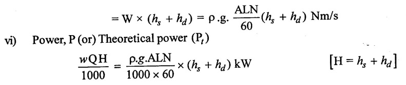
(v) Work input/sec = Weight of water lifted /sec (or) delivered/sec × total height of water lifted.
2. Double acting reciprocating pump:
In a double acting reciprocating pump, the cross sectional area of the cylinder varies at both side of the piston, 

This difference in areas in shown in figure 4.46. The difference has regulated due to the presence of the piston rod.
(vi) The actual power required to drive the pump is more than the theoretical power due to frictional and other losses in the pump.
The ratio of theoretical power to the actual power is called as the efficiency of pump (η).
3. Co-efficient of discharge (Cd) and slip:
The actual discharge from the reciprocating pump is always less than the theoretical discharge.
The reasons for less discharge are:
a) Water leakage from the valves, glands and piston packing.
b) Delay in opening and closing of suction and delivery valves due to inertia.
c) Incomplete filling of the cylinder.
1. Co-efficient of discharge (Cd):
It is the ratio of the actual discharge to the theoretical discharge (Cd).
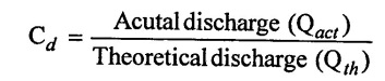
The co-efficient of discharge (Cd) is nothing but the volumetric efficiency when it is expressed in percentage.
2. Slip:
Slip is the difference between the theoretical discharge and actual discharge.
Hence slip is given by
Slip = Qth - Qact
The percentage of slip can be expressed as
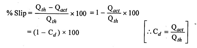
3. Negative Slip:
In most of the reciprocating pumps, the actual discharge is less than the theoretical discharge. It means that the value of co-efficient of discharge (Cd) is less than the unity. However, in some cases, the actual discharge (Qact) may be greater than the theoretical discharge (Qact > Qth) and the slip in these cases becomes negative. The negative slip takes place when
(i) There is direct connection between suction and delivery sides before the end of suction stroke.
(ii) Momentum of liquid in the suction side of is large enough to keep open the delivery valve before the beginning of delivery stroke and
(iii) High speed pumps long suction pipe and short delivery pipe.
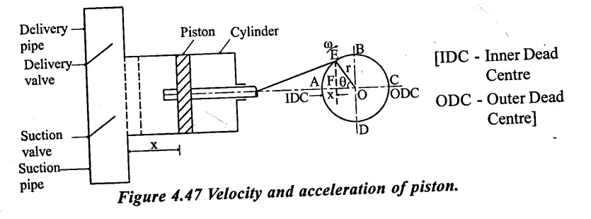
7. Variation of velocity and acceleration in the suction and delivers pipes due to acceleration of the piston
The piston moves forward and backward when the crank rotates. A the inner and outer dead centers, the velocity of the piston is zero. The velocity of the piston is maximum at the centre of the cylinder in each stroke of the piston. Hence, the velocity of piston is zero at the start of the stroke, it becomes maximum at the centre of the stroke and then it reduces to zero at the end of the stroke. This means, that the piston has an acceleration at the beginning of the stroke to the centre and retardation from the centre to the end of the stroke. As the water in the cylinder is in contact with the piston, resulting water in the cylinder is in contact with piston, resulting water in suction and delivery pipe to have the same acceleration and retardation which is acting on the piston. The acceleration and retardation of the water in the cylinder will cause the changes in water pressure in the cylinder.
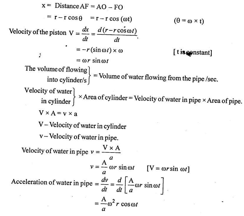
As shown in figure 4.47 the crank is rotating with a constant angular speed. If the motion of the piston is assumed to be a simple harmonic motion, then the distance (x) travelled by the piston in time (t).
ω = Angular speed of the crank in rad/s.
A = Area of the cylinder
a = Area of the pipe [Suction or delivery pipe]
l = Length of the pipe [suction or delivery pipe]
r = Radius of the crank.
In the beginning, the crank is at A (IDC) and the piston in the cylinder is at a position shown by dotted lines. The crank is rotating with an angular velocity @ and let in time 't' seconds, the crank turns through an angle θ [in radians] from A. The displacement of the piston in time 't' is x as shown in figure 4.47.
θ = ω × t
[θ - Angle turned by crank in radians in time 't']
The distance x travelled by the piston is given of
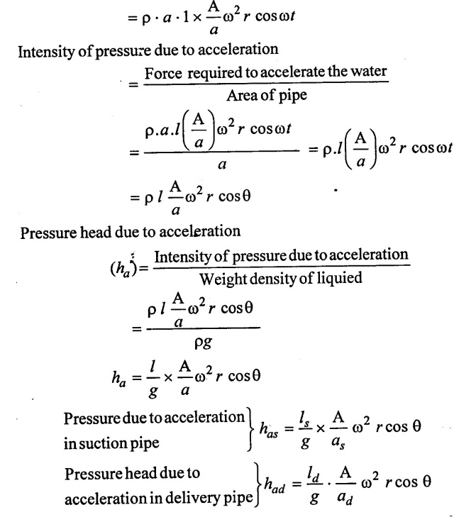
Mass of water in pipe = ρ × Volume of water in pipe
= ρ × Area of pipe × Length of pipe
= ρ × a × 1
Force required to accelerate the water in
The pipe = Mass of water in pipe × Acceleration of water in pipe.
ls - Length of suction pipe
A - Area of cylinder
as - Area of suction pipe.
ld - Length of delivery pipe.
ad - Area of delivery pipe.
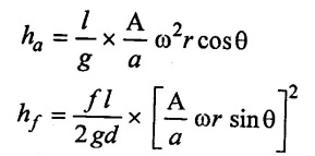
The pressure head due to acceleration varies with θ. The values of (ha) for different values of θ are
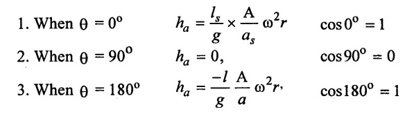
Maximum pressure head due to acceleration
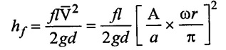
8. Effect of variation of velocity on friction in the suction and delivery pipes
Loss of head due to friction in pipes when,
Water flows with velocity (V) is given by
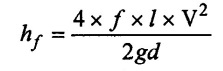
Where,
ƒ = Co-efficient of friction
l = Length of pipė
d = Diameter of pipe
The velocity (V) of water in the pipe due to acceleration of the piston in the cylinder of a reciprocating pump is given by
Putting this value of velocity in the head loss due to friction.
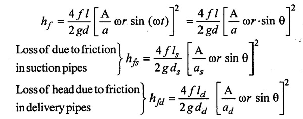
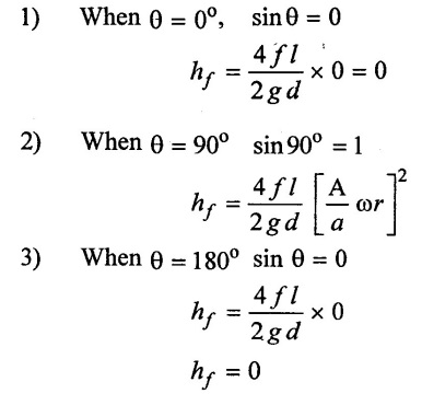
The loss of head due to friction in varies with θ as
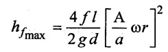
Maximum value of loss of head due to friction
9. Indicator diagram:
The indicator diagram for a reciprocating pump is a graph between the pressure head in the cylinder and the distance travelled by piston from inner dead centre (IDC) for one complete revolution of the crank (stroke length). As the maximum distance travelled by the piston from inner dead centre for one complete revolution of the crank is equal to the stroke length and hence the indicator diagram is a graph between pressure head and stroke length of the piston for one complete revolution. The pressure head is drawn on y- axis and stroke length in the crank angle an x-axis. It should the pressure head of the liquid in the cylinder corresponding to any position during the suction and delivery stroke.
1. Ideal indicator diagram
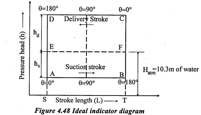
It is the graph between pressure head pressure head in the cylinder and stroke length of piston for 1 complete revolution of crank under ideal conditions.
Consider an ideal indicator diagram as shown in Figure 4.48 in which atmospheric pressure head is 10.33 m of water (Line EF).
Let,
L = Stroke length in m
hs & hd suction and delivery head in m.
Hatm = Atmospheric pressure head= 10.33 m of water
The pressure head during suction stroke is represented by a horizontal line AB which is below the line EF by a height hs.
Similarly, the pressure head during delivery stroke is represented by a horizontal line CD which is above the line EF by a height hd.
It means, for one complete revolution of the crank, the pressure head in the cylinder is represented by ABCDA. This diagram is called as Ideal indicator diagram.
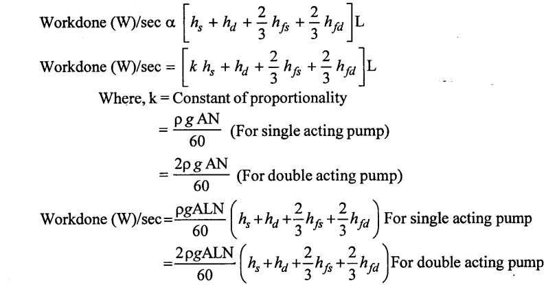
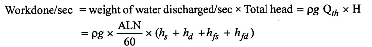
As the workdone by the pump per second is,
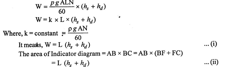
From equations (i) and (ii), it is clear that the work done by the pump is proportional to the area of indicator diagram i.e., work done by pump is directly proportional to area of indicator diagram
2. Effect of Acceleration in suction and Delivery pipes on Indicator Diagram
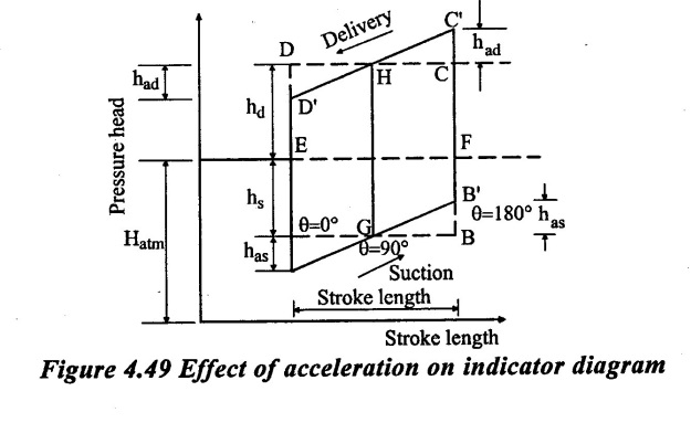
From figure 4.49 shown the effect of acceleration in suction and delivery pipe on indicator diagram.
It is clear that, the indicator diagram changes from ABCD to A' B' C' D' due to acceleration in suction and delivery pipe.
The area of indicator diagram remain unchanged. The acceleration head increases the negative head at the beginning of suction stroke.
a) For suction pipe:
Let hs = Suction head in m
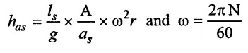
has = Acceleration head in suction pipe in m.
ls = Length of suction pipe in m
as = Cross-sectional area of suction pipe in m2
Hs = Pressure head in cylinder during suction stroke in m of water.
During the suction stroke, the piston starts to move outwards. At the beginning of suction stroke it should create the negative pressure equal to the suction head (has) as well as accelerate the fluid.
The total negative pressure head of the beginning of suction stroke (i.e) A' is (hs + has).
The absolute pressure head at the beginning of suction stroke should not fall below the vapour pressure head to avoid separation.
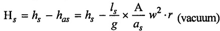
(i) At the beginning of suction stroke (θ = 0°)
The negative pressure (vacuum) head is,

Absolute pressure head is,
Habs = Hatm - (hs + has) (absolute)
(ii) At the middle of suction stroke (θ = 90°)
The negative pressure (vacuum) head is, Hs = hs + has = hs + 0 = hs (vacuum)
Absolute pressure head is, Habs = Hatm - has (absolute)
(iii) At the end of suction stroke (θ =180°)
The negative pressure (vacuum) head is,
Absolute pressure head is, Habs = Hatm – (hs - has) (absolute)
b) For delivery pipe:
Let,
hd = Delivery head in m
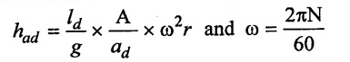
had = Acceleration head in delivery pipe in m
ld = Length of delivery pipe in m
ad = Cross-sectional area of the delivery pipe in m2
Hd = Pressure head in cylinder during delivery stroke in m of water.
At the beginning of delivery stroke the liquid in the delivery pipe is accelerated, while at the end of delivery stroke the liquid is retarded.
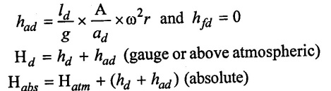
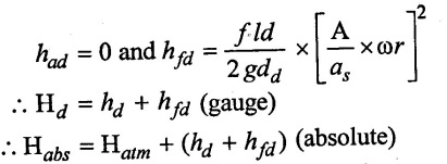
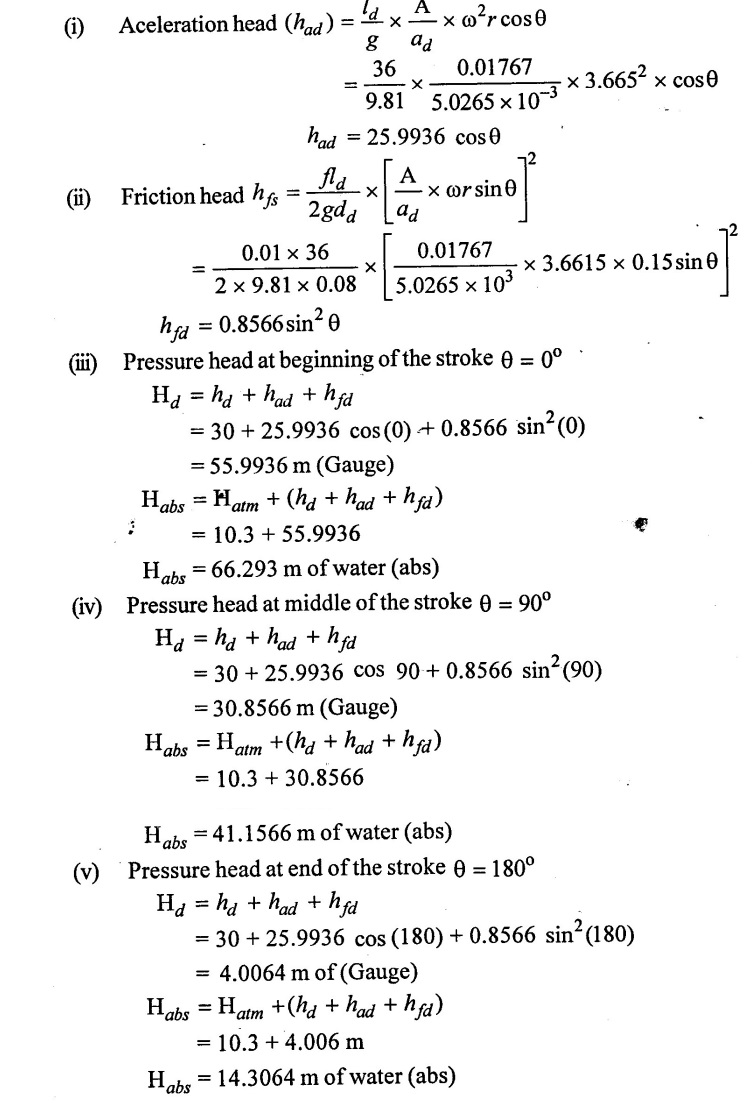
(i) At the beginning of delivery stroke (θ = 0°)
The gauge pressure head is,
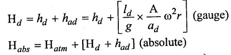
(ii) At the middle of delivery stroke (θ = 90°)
The gauge pressure head is,
Hd = hd + had = hd + 0 = hd (gauge)
Habs = Hatm + hd (absolute)
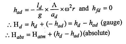
(iii) At the end of delivery stroke(θ = 180°)
The gauge pressure head is,
The absolute pressure head at the end of delivery stroke should not less than vapour pressure head to avoid separation.
3. Effect of friction in suction and delivery pipes on indicator diagram
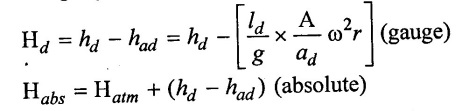
From the previous equations, the loss of head due to friction in suction and delivery pipes are,
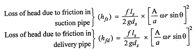
The variation of hfs and hfd with respect to θ is parabolic in nature. The indicator diagram during suction and delivery stroke with friction in pipe is shown in figure 4.50.
Area of parabola AGB and CHD represents the work done against friction in suction and delivery pipe.
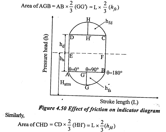
Where, AB = CD = Length of stroke
4. Effect of acceleration and friction in suction and delivery pipes on indicator diagram
The acceleration head (ha) and friction head (hf) at any instant in suction and delivery pipes of reciprocating pump is as follows:
a) For suction stroke
The pressure head in the cylinder during suction stroke at any instant θ is given by.
Hs = hs + has + hfs
(i) At in beginning of suction stroke (θ = 0°)
(ii) At the middle of suction (θ = 90°)
(iii) At the end of suction stroke (θ = 180°)
(b) For delivery stroke
The pressure head.in the cylinder during delivery stroke at any instant θ is given by
Hd = hd + had + hfd
(i) At the beginning of delivery stroke (θ = 0°)
(ii) At the middle of delivery stroke (θ = 90°)
(iii) At the end of delivery stroke (θ = 180°)
5. Effect of acceleration and friction on indicator diagram
The complete indicator diagram including the effect of acceleration and friction in suction and delivery is shown in figure 4.51.
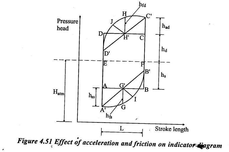
Total area of indicator diagram given by,
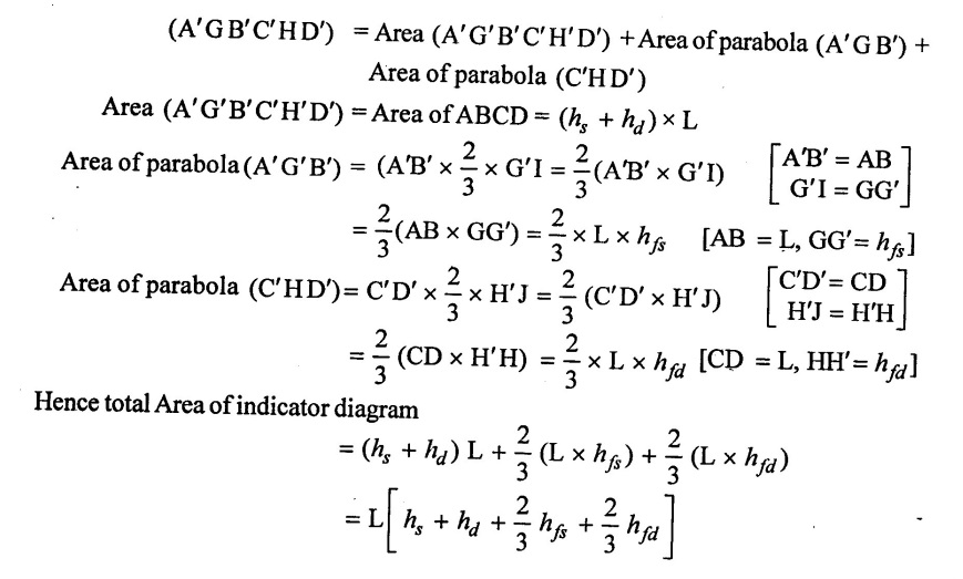
As work done by the pump is directly proportional to area of indicator diagram
10. Maximum speed of reciprocating pump
The main consideration for finding the maximum speed of reciprocating pump is that, the pressure in the cylinder during suction and delivery stroke should not falls below the vapour pressure of liquid.
If it falls below the vapour pressure of liquid, there will be the formation of bubbles and cavitations will take place.
Hence, the continuous flow of liquid will not exist and separation will take place.
The pressure at which separation takes place is known as separation pressure and head corresponding to its separation head (hsep).
The limiting value of separation head is,
hsep = 7.8 m below atmospheric pressure head.
= 10.3 - 7.8 = 2.5 m of water (absolute)
(A) During suction stroke
During suction stroke, the separation can take place at the beginning of stroke only. The limiting condition is,
hsep = Hatm - (hs + has)
⸫ has = Hatm - hs - hsep
Now the from acceleration head, value of max speed can be determined
(B) During Delivery Stroke
During the delivery stroke, the separation will take place only at the end of the stroke. Hence the limiting condition is,
hsep = Hatm + (hd – had)
⸫ had = Hatm – hd - hsep
Now from acceleration head, value of maximum speed can be determined.
11. Air Vessels
An air vessel is a closed container having air at the upper portion of the container and liquid in the lower portion of the container.
The figure 4.52 shows the reciprocating pump fitted with the air vessels near the suction and delivery valve.
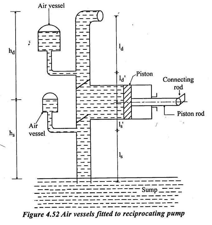
At the base of an air vessel there is an opening through which the liquid enters the air vessel. Hence, the air in the upper portion gets compressed. This compressed air forces the liquid as soon as the pressure in the pipe falls. The air vessel act as an intermediate reservoir for the system. When the air vessel fitted to the suction pipe, during the first half the piston moves with acceleration.
Hence, the velocity of liquid in the suction pipe is more than mean velocity, therefore the discharge of water entering the cylinder will be more than the mean discharge. This excess quantity of liquid will be supplied by the air vessel in such way that the velocity in the pipe becomes equal to the mean discharge. During the second half of the suction stroke, the piston moves with retardation.
Hence the velocity of liquid in the suction pipe is less than the mean velocity, therefore the discharge of water entering the cylinder will be less than mean discharge. The excess quantity of liquid will enter the air vessel and the velocity of liquid in suction pipe will be equal to the mean velocity. The liquid stored in the air vessel will be used in the next cycle. The same procedure continues during the delivery stroke to keep the flow uniform.
The purpose of filling an air vessel to the suction and delivery pipe is as follows.
(i) To ensure continuous supply of liquid at uniform rate without affecting by any type of fluctuations.
(ii) It reduces the acceleration head and friction head there by reducing the workdone by the pump.
(iii) The power required to drive the pump is also reduced.
(iv) It allows the pumps to run with higher speed without any danger of separation.
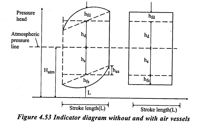
Figure 4.53 shows the indicator diagram without and with fitting adequate air vessel.
ls = Length of suction pipe below air vessel
l's = Length of suction pipe between cylinder and air vessel
ld = Length of delivery pipe beyond air vessel
l'd =Length of delivery pipe between cylinder and air vessel
has = Pressure head due to acceleration in suction pipe.
had = Pressure head due to acceleration in delivery pipe
hfs = Loss of head due to friction in suction pipe below air vessel.
h'fs = Loss of head due to friction in suction pipe between cylinder and air vessel.
hfd = Loss of head due to friction in delivery pipe between cylinder and air vessel.
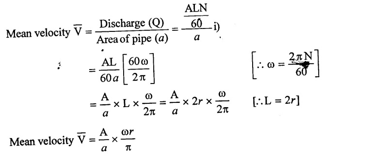
The velocity of flow of water in the length ld and ls will be equal to mean velocity of flow. It is calculated as,
The velocity of water in suction and delivery pipe for length ls' and ld' due to acceleration and retardation is
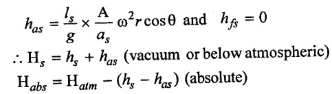
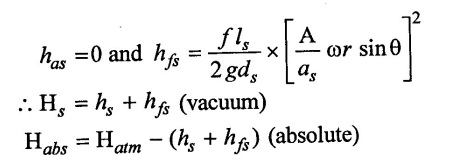
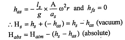
(a) Pressure head in the cylinder during suction stroke when air vessel fitted is,
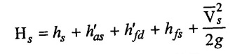
(b) Pressure head in the cylinder during delivery stroke when air vessel is fitted.
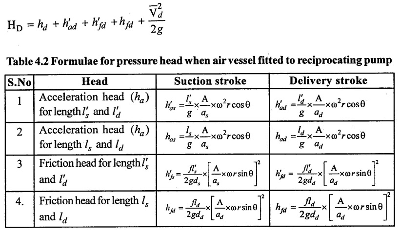
The value of acceleration head and friction head depends upon the crank positions (θ) for the following cases,
(i) At the begining of suction or delivery stroke,
θ = 0°, cos 0 = 1, sin 0 = 0
(ii) At the middle of suction or delivery stroke,
θ = 90°, cos 90 = 0, sin 90 = 1
(iii) At the end of suction or delivery stroke,
θ = 180°, cos 180 = - 1, sin 180 = 0
(c) Work done by reciprocating pump with air vessel
The work done by reciprocating pump fitted with air vessel to suction and delivery pipe is given by,
(d) Work saved by fitting as air vessel
The significance of fitting an air vessel is that, it reduces the loss of head due to friction in suction and delivery pipe.
This leads to saving in certain amount of energy which can be calculated by finding work against friction without and with air vessel. Refer figure 4.52 for indicator diagram without and with air vessel.
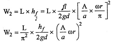
(i) Work done against friction without air vessel
The workdone by pump against friction per stroke is equal to area of the indicator diagram due to friction. It is given by
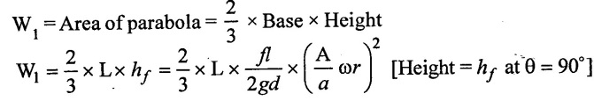
(ii) Work done against friction with air vessel
If air vessel with adequate capacity is fitted to suction or delivery pipe, the velocity of flow through pipes is uniform and equal to mean velocity.
The head loss due to friction with air vessel is,
This head loss is in depend to θ and hence indicator diagram is rectangle.
The work done by pump per stroke against friction,
W2 = Area of rectangle = Base × Height
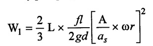
(iii) Work saved in a single acting reciprocating pump:
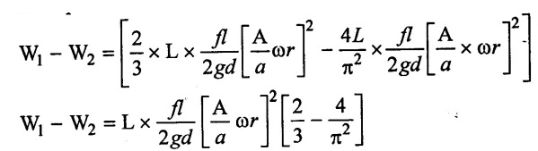
The saving in a work done is calculated by subtracting equation W1 to W2.
Work saved/stroke = W1 – W2
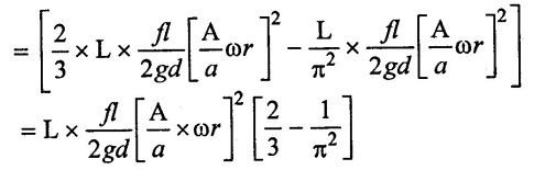
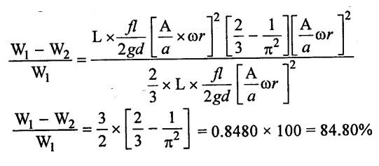
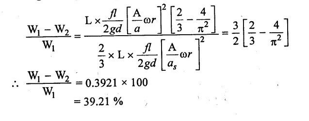
The percentage saving in work is,
(iv) Work saved in a double acting reciprocating pump
The work done by pump against friction per stroke is same as for single acting pump.
The mean velocity for double acting cylinder is,
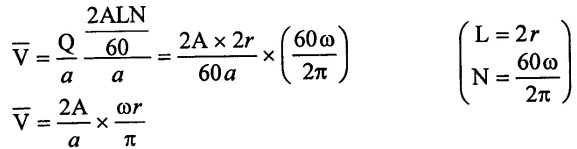
Loss of head due to friction is,
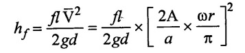
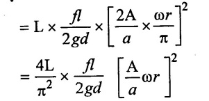
Work done due to friction per stroke is,
W2 = Area of rectangle = L × hf
Work saved per stroke is.
Percentage saving inwork per stroke is,
(e) Discharge of liquid into and from the air vessel
1. Single acting pump
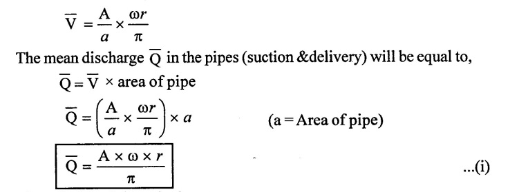
Let the air vessel is fitted to both suction and delivery pipe of a single acting reciprocating pump. Due to air vessel, the liquid insuction and delivery pipes beyond air vessel will be moving with a constant mean velocity. This mean velocity in the pipe is given by
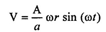
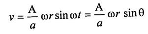
The velocity of piston in the cylinder at any instant is given by
v = ωr × sin (ωt)
= ωr × sinθ (ωt = 0)
Hence instantaneous discharge to or from the cylinder of the pump will be as,
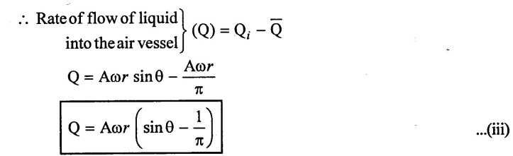
The difference of the two discharges given by equation (ii) & (i) will be equal to the rate of flow of liquid into or from the air vessel.

(i) For air vessel fitted to delivery pipe:
The liquid will be flowing into the air vessel, if rate of flow (Q) is positive. But if rate of flow (Q) is negative, then liquid will flow from the air vessel. If rate of flow (Q) is zero, then no flow is taking place from or to the air vessel.
(ii) For air vessel fitted to suction pipe:
If rate of flow (Q) is positive, then n the liquid is flowing from the air vessel. If rate of flow (Q is negative, then liquid is flowing into the air vessel. For no flow of liquid into or from the air vessel, the rate of flow(Q) should be zero.
2. For double acting pump
The discharge for double acting pump is
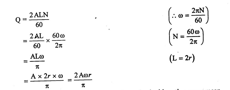
The above discharge is the mean discharge. Hence for double acting pump mean discharge 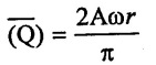
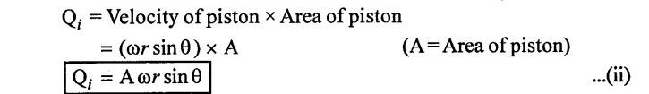
But the instantaneous discharge (Qi) to or from the cylinder of the pump will be
Qi = Velocity of piston × Area of piston
Qi = ωr sinθ × A
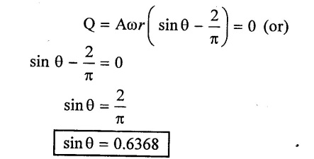
Qi = A ωr sinθ
Hence rate of flow of liquid into air vessel
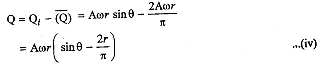
(i) For air vessel fitted to delivery pipe:
It rate of flow (Q) is positive, the liquid is flowing into the air vessel fitted to delivery pipe. It rate of flow (Q) is negative, than liquid is flowing from the air vessel. If rate of flow (Q) is zero then no flow is taking place into or from the air vessel.
(ii) For air vessel fitted or suction pipe:
It rate of flow (Q) is positive, the liquid is flowing from the air vessel fitted to suction pipe. If rate of flow (Q) is negative, the liquid is flowing into the air vessel. If no flow of liquid into or from the air vessel, the rate of flow (Q) should be zero.
12. Separation
Separation or cavitations in a reciprocating pump is that phenomenon by which the steady & continuous flow of luquid is obstructed due to the emergence of air and dissolved gases in the flowing liquid.
The following methods are to be adopted to prevent the separation.
(i) The vacuum or suction pressure inside the cylinder should not go beyond the permissible limit.
(ii) To provide air vessels both on the suction & delivery sides,
(iii) The pump should not run too fast.
(iv) The suction lift should not be increased beyond the permissible value.
13. Solved Examples based on reciprocating pump
Example : 21
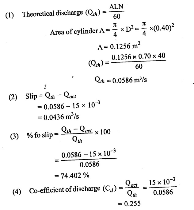
A single acting reciprocating pump runs at 40 rpm the diameter and stroke are 40 cm and 70 cm respectively the discharge is 15 litres/s of water find
(i) Theoretical discharge
(ii) Slip and percentage of slip
(iii) Co-efficient of discharge
Given data:
Speed (N) = 40 rpm
Diameter of piston (D) = 40cm = 0.40m
Stroke length (L) = 70cm = 0.70m
Discharge (Qact) = 15 lit/sec = 15 × 10−3 m3/s
To find:
(i) Theoretical discharge (Qact)
(ii) Slip and % of slip
(iii) Co-efficient of discharge (Cd)
Solution:
Result:
(1) Theoretical discharge (Qth) = 0.0586 m3/s
(2) Slip = 0.0436 m3/s
(3) % of slip = 74.402%
(4) Co-efficient of discharge (Cd) = 0.255
Example : 22
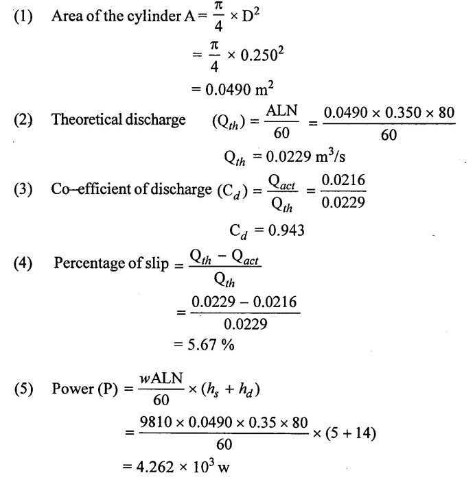
A single acting reciprocating pump runs at 80 rpm delivers 1.3 m3 of water per minute. The diameter of the piston is 250mm and stroke length is 350mm the suction and delivery heads are 5m and 14 m respectively. Determine a) Theoretical discharge b) Co-efficient of discharge (c) % of slip d) Power required to run the pump.
Given data:
Speed of the pump (N) = 80 rpm
Diameter of the piston (D) = 250mm = 0.250m
Stroke length (L) = 350mm= 0.35 m
Actual discharge (Qact) = 1.3 m3/min = 0.0216 m3/s
Suction head (hs) = 5m
Delivery head (hd) = 14 m
To find:
(1) Theoretical discharge (Qth)
(2) Co-efficient of discharge (Cd)
(3) % of slip
(4) Power required to run the pump
Solution:
Result:
(1) Theoretical discharge (Qth) = 0.0229 m3/s
(2) Co-efficient of discharge (Cd) = 0.943
(3) % of slip = 5.67%
(4) Power required to run the pump (P) = 4.262 × 10³ w
Example : 23
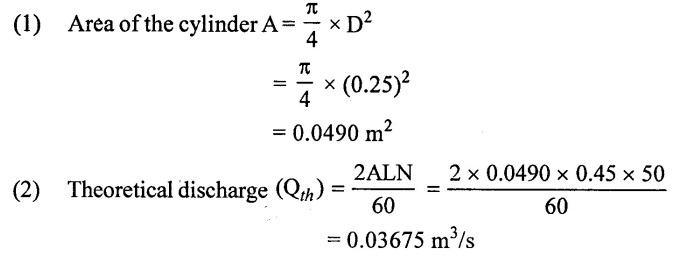
A double acting reciprocating pump discharge 0.02m3/s of water at 50 rpm. The diameter and stroke are 25 cm and 45cm respectively. The suction and delivery heads are 6m and 32 m respectively. Calculate a) Slip b) Power required to drive the pump.
Given data:
Actual discharge (Qact) = 0.02m3/s
Speed (N) = 50 rpm
Diameter (D) = 25cm = 0.25 m
Stroke length (L) = 45 cm = 0.45 m
Suction head (hs) = 6m
Delivery head (hd) = 32 m
To find:
(1) Slip
(2) Power required (P)
Solution:
(3) Slip = Qth - Qact
= 0.03675 - 0.02
Slip = 0.01675
Result:
(1) Theoretical discharge (Qth) = 0.03675 m3/s
(2) Slip = 0.01675
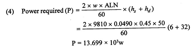
(3) Power required P = 13.699 × 10³w
Example : 24
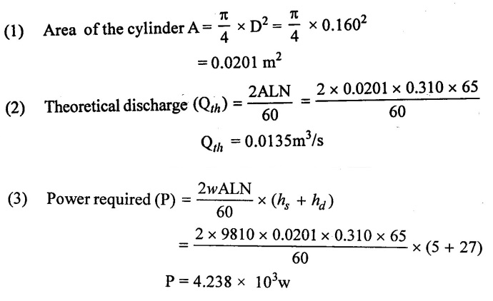
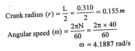
A double acting reciprocating pump has a stroke of 310 mm and a piston of diameter 160mm. The delivery and suction head are 27mm and 4m respectively including friction heads. If the pump is working at 65 rpm. Find the power required to drive the pump with 80%.
Given data:
Stroke length (L) = 310mm= 0.310 m
Piston diameter (D) = 160mm=0.160m
Delivery head (hd) = 27 m
Suction head (hs) = 5m
Efficiency (η) = 80%
Speed (N) = 65 rpm
To find:
Power required (P)
Solution:
Result:
Power required (P) = 4.238 × 10³w
Example: 25
A reciprocating pump has a plunger of diameter 120mm and stroke length 210mm and it runs at 45 rpm. The suction pipe is 52mm in diameter and 6m long. If separation takes place. At pressure head of 77m of water vacuum. Determine the maximum height at which the pump can be installed without causing separation.
Given data:
Diameter of plunger (D) = 120mm = 0.120m
Stroke length (L) = 210 mm = 0.210 m
Speed (N) = 45 rpm
Suction pipe diameter (ds) = 52mm = 0.052 m
Length of suction pipe (1) = 6m
To find:
Maximum height at which pump canbe in stalled without causing separation.
Solution:
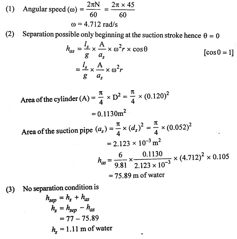
Result :
Suction head without separation (hs) = 1.11 m of water
Example : 26
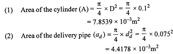
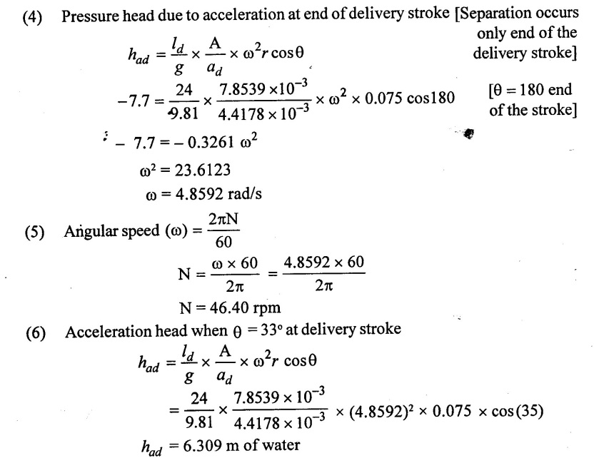
In a single acting reciprocating pump the bore and stroke are 100mm and 150mm respectively. The static head requirement are 4 m suction and 18m delivery. If the pressure at the end of delivery is atmospheric. Calculate the operating speed the diameter of the delivery pipe is 75mm and length of the delivery pipe is 24m. Determine the acceleration head at θ = 35° from the start of delivery.
Given data:
Diameter of cylinder (D) = 100mm = 0.1m
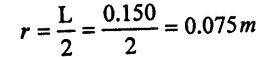
Stroke length (L) = 150mm = 0.15m
Static head (or) suction head (hs) = 4m
Delivery head (hd) = 18m
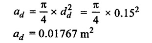
Diameter of delivery pipe (dd) = 75mm = 0.075 m
Length of delivery pipe (ld) = 24m
To find:
(1) Operating speed (N)
(2) Acceleration head at θ = 33°
Solution:
(3) Presure head in the cylinder at the end of delivery stroke is equal to atmospheric head
Hatm = hd + had
10.3 = 18 + had
had = 10.3 - 18
had = -7.7 m of watr
Result:
(1) Speed (N) = 46.4024 rpm
(2) Acceleration head when θ = 33° had = 6.309 m of water.
Example : 27
The cross-section area of piston is 3/2 times the delivery pipe. The delivery pipe is 30m long and it rises. Up wards at a slop of 1:4. If the plunger has an acceleration of 2.7 m/s2 at the end of stroke. The separation occurs when the pressure fully below the 2.5 m of water absolute. Find whether the separation will take place it so at which section pipe. Take atmosphere pressure head as a 10.3m of water.
Given data:
Area of piston A= 3/2 area of delivery pipe (ad)
Slope = 1:4
Acceleration (ω2r)=3.7m/s2
Length of delivery pipe (ld) = 30m
Separation head (hsep) = 2.5 m of water
Atmospheric pressure head (Hatm) = 10.3 m of water
To find:
(1) Check whether sepatation will take place of not
(2) Length at which separation occurs
Solution:
(1) Delivery head (hd) = slope × length
= 1/4 × 30
= 7.5 m

Result :
Separation occurs and length (l) = 24.76 m
Example : 28
A single acting reciprocating pump has a plunger diameter 12cm and stroke length 22cm. The suction pipe is 6.8 m long and 5.5 cm in diameter and suction lift is 3.5m. If the separation occurs at the 2.5 m of water absolute. Find the maximum speed of which pump can be run with out separation in the suction pipe. Take atmosphere pressure head as 760mm of Hg
Given data:
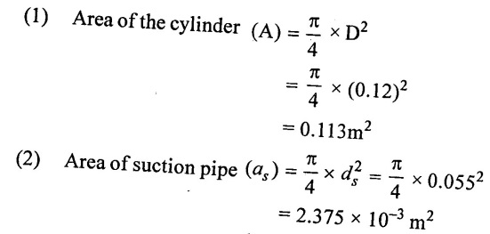
Diameter of cylinder (D) = 12cm = 0.12m
Stroke length (L) = 22cm = 0.22m
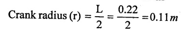
Length of suction pipe (ls) = 6.8 m
Diameter of suction pipe (ds) = 5.5cm = 0.055m
Suction head (hs) = 3.5 m
Separation head (hsep) = 2.5 m
Atmospheric pressure head (Hatm) = 760 mm of Hg
= 760/1000 × 13.6 = 10.336 m of water
To find:
Maximum speed at which pump run without separation
Solution:
(3) Acceleration head at beginning of suction stroke becuase separation occurs beginning of stroke hence θ = 0°
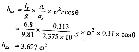
(4) Absolute pressure head at beginning of suction stroke
Hs = Hatm - (hg + has)
To avoid separation, the absolute pressure head not fall below the separation head.
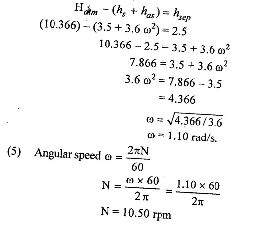
Result:
N = 10.50 rpm
Maximum speed without separation N = 10.50 rpm.
Example : 29
The piston diameter and stroke length of a double acting single reciprocating pump are 15 cm and 30cm respectively. The centre of the pump is 4.0m and level in the sump and 30m below the delivers water level. Both the suction and delivery pipes are same diameter of 80 mm and are 6m and 36m long respectively. If the pump is working at 35 rpm. Determine the pressure heads on the piston at the beginning, middle and end of both suction and delivery strokes and the power required to derive pump, if the mechanical efficiency is 80%.
Atmospheric pressure = 10.3 m of water.
Darcy's friction factor = 0.01
Given data:
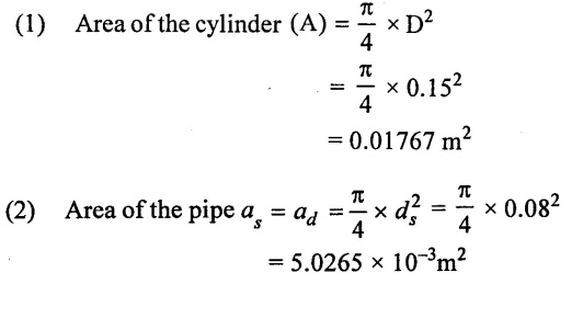
Diameter of piston (D) = 15cm = 0.15m
Length of stroke (L) = 30cm= 0.3 m
Suction head (hs) = 4m
Delivery head (hd) = 30m
Diameter of both pipe (ds) = (dd) = 0.08m
Length of delivery pipe (ld) = 36 m
Length of suction pipe (ls) = 6 m
Speed (N) = 
Mechanical efficiency ηm = 0.8
Atmosheric pressure head (Hatm) = 10.3 m of water
Friction factor (f) = 0.01 [4f = f = 0.01]
To find:
(1) The Pressure head at beginning, middle and end of the both duction and delivery strokes.
(2) Power required to drive the pump
Solution:
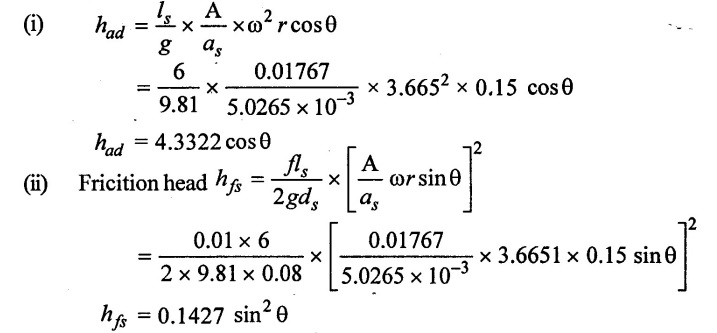
(3) Calculate pressure heads on the piston during suction stroke
(iii) Pressure head on the piston beginning of suction stroke θ = 0
Hs = hs + has + hfs
= 4 + 4.332 cos θ + 0.1427 sin2 θ
= 8.3322 m [vacuum]
Habs = Hatm - (hs + has + hfs) = 10.3 - 8.3322
Habs = 1.9678 m of water (absolute)
(iv) Pressure head on the piston of middle of suction stroke θ = 90°
Hs = hs + has + hfs
= 4 + 4.3322 cos (90) + 0.1427 sin2 (90)
= 4.1427 m (vacuum)
Habs = Hatm - (hs + has + hfs) = 10.3 - 4.1427
Habs = 6.1573 m of water (abs)
(v) Pressure head on the piston at end of suction stroke θ = 180°
Hs = hs + has + hfs
= 4 + 4.3322 cos (180) + 0.1427 sin2(180)
= -0.3322 m (vacuum)
Habs = Hatm - (hs + has + hfs) = 10.3 - (-0.3322)
Habs = 10.6322 of water (abs)
(4) Pressure head on the piston during delivery stroke
 (5) Power required (P)
Workdone = w QH
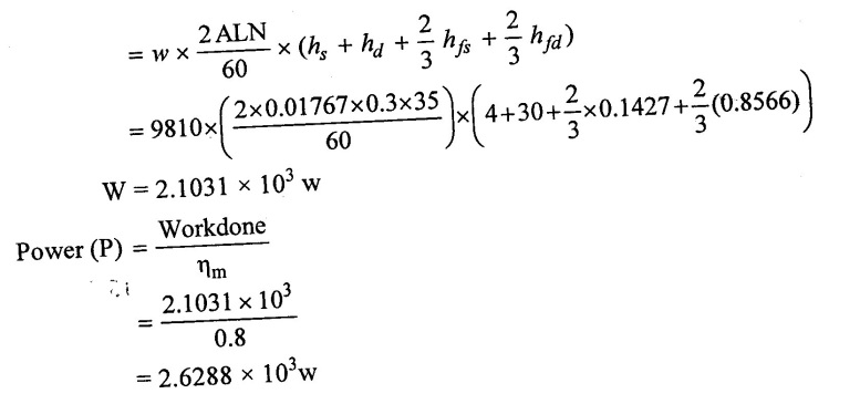
Result :
Power required (P) = 2.6288 × 10³w
Example : 30
A cylinder bore diameter of a single acting pump is 160 mm and stroke is 310 mm. The pump runs at 40rpm and lifts water through height of 20m. The delivery pipe is 22 m long and 120mm in diameter. Find theoretical discharge and theoretical power required to run the pump. If the actual discharge 3.8 lps. Determine the % of slip, acceleration heads at the beginning, middle and end of the delivery stroke.
Given data:
Diameter of the piston (D) = 160mm = 0.160 m
Stroke length (L) = 310mm = 0.310 m
Speed (N) = 40 rpm
Total head (hs + hd) = H = 26 m
Length of delivery pipe (ld) = 22 m
Diameter of delivery pipe (dd) = 120 mm = 0.12 m
Discharge (Q) = 3.8 / Ps = 3.8 × 10³ m3/s
To find:
(1) Theoretical discharge (Qth) and theoretical power (P).
(2) % of slip
(3) Acceleration head at beginning, middle and end of the delivery stroke.
Solution:
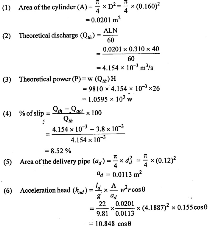
(7) Acceleration head at beginning of delivery stroke θ = 0°
had = 10.848 cos 0
= 10.848 m
(8) Acceleration head to middle of stroke θ = 90°
had = 10.848 cos 90°
had = 0
(9) Acceleration head at end of stroke θ = 90°
had = 10.848 cos 180°
had = 10.848 m
Result :
(1) Theoretical discharge (Qth) = 4.154 × 10⁻³ m3/s
(2) Theoretical power (P) = 1.0595 × 10³w
(3) % of slip = 8.52%
Example: 31
For a single acting reciprocating pump. Piston diameter 150mm. Stroke length is 300mm rotational speed is 50 rpm. The pump is required to lift water to a height of 18 m. Determine the theoretical discharge also if the actual discharge is 4.0 lit/sec and the mechanical efficiency is 80%. Also determine the volumetric efficiency, slip, and the power required.
Given data:
Piston diameter (D) = 150mm = 0.15 m
Stroke length (L) 300 mm = 0.3 m
Rotatical speed (N) = 50 rpm
Height (H) = 18 m
Actual discharge (Qact) = 4 lps = 4 × 10⁻³ m3/s
Mechanical efficiency (ηm) = 0.8
To find:
(i) Volumetric efficiency (ηv)
(ii) Theoretical discharge (Qth)
(iii) Slip
(iv) Power required (P)
Solution:
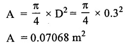
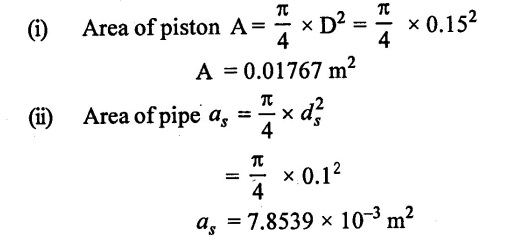
(1) Cross-sectional area of piston is
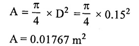
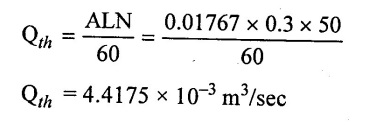
(2) The theoretical discharge
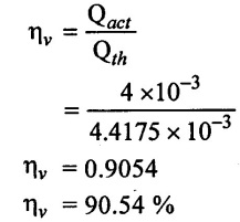
(3) The volumetric efficiency
(4) Slip of reciprocating pump
Slip = Qth - Qact
= 4.4175 × 10⁻³ - 4 × 10⁻³
Slip = 4.175 × 10⁻⁴ m3/sec
(5) Power required to drive the pump
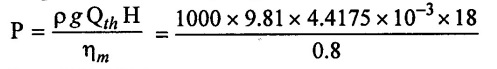
P = 975.0526 w
P = 0.975 kw
Result:
(1) Theortical discharge Qth = 4.4175 × 10⁻³ m3/sec
(2) Volumetric efficiency ηv = 90.54%
(3) Slip = 4.175 × 10⁻⁴ m3/sec
(4) Power P = 0.975 kw.
Example : 32
A single cylinder double acting reciprocating pump has a piston diameter of 300mm and stroke length of 400mm when the pump runs at 45 rpm. It discharge 0.039 m3/s under a total head 15m. What be the volumetric efficiency, work done per second and power required if the mechanical efficiency of the pump 75%.
Given data:
Piston diameter D = 300mm = 0.3 m
Stroke length L = 400 mm = 0.4 m
Speed (N) = 45 rpm
Discharge (Q)act = 0.039 m3/sec
Head (H) = 15 m
Mechanical efficiency ηmech = 0.75
To find:
(1) Volumetric efficiency (ηv)
(2) Workdone per second W/s
(3) Power required (P)
Solution:
(1) Cross-sectional ara of thepistonor cylinder
(2) Theoretical discharge through double acting reciprocating pump
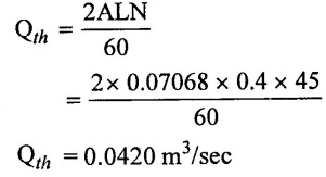
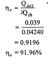
(3) Volumetric efficiency
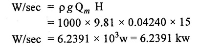
(4) Work done per second
(5) Power required
Result :
(1) Volumetric efficiency ηv = 91.96%
(2) Workdone per second wD/s = 6.239 kw
(3) Power required P = 8.3188 kw.
Example : 33
The cylinder of a single acting reciprocating pump is 15cm in diameter and 30cm in stroke. The pump running at 30 rpm and discharge of water to a height of 12m. The diameter and length of the delivery pipe are 10cm and 30 m respectively. If a large air vessel is fitted in the delivery pipe at a distance of 2m from the centre of the pump. Find the pressure head in the cylinder.
(i) At the beginning of the delivery stroke
(ii) In the middle of the delivery stroke take ƒ = 0.01.
Given data:
Diameter (D) = 15cm = 0.15m
Length (L) = 30cm= 0.3m
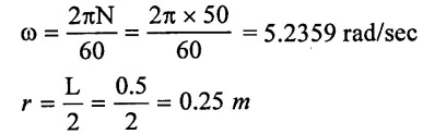
Speed (N) = 30 rpm
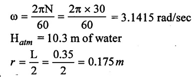
Angular speed 
Height (hd) = 12m
Diameter of the delivery (dd) = 10cm = 0.1m
Length of the delivery (L) = 30m
Co-efficient of friction (f) = 0.01
Distance l'd = 2m
To find:
Pressure head
Solution:
(1) Calculate the pressure in the cylinder at the beginning of the delivery stroke
(i) Cross-sectional area of the cylinder or piston
(ii) Cross-section area of the delivery pipe
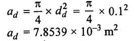
(iii) Length of delivery pipe above air vessel is
ld = l − l'd = 30 - 2 = 28m
(iv) Pressure head between cylinder and air vessel

(v) Loss of head due to friction in delivery pipe for length ld
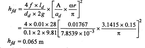
(vii) The velocity head at the outlet of delivery
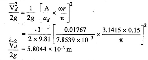
(viii) Pressure head at beginning of the delivery stroke
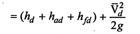
= 12 + 0.6790 + 0.065 + 5.8044 × 10−3
= 12.7498 m
(2) Calculate the pressure head the middle of delivery stroke θ = 90°
(i) Pressure head of length l'd
had = 0
Loss of pressure head due to friction in delivery pipe for length l'd
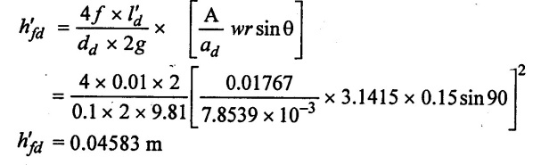
(iii) Pressure head in the cylinder in the middle of delivery
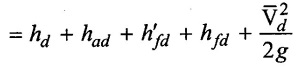
= 12 + 0 + 0.04583 + 0.065 +5.8044 × 10-3
= 12.1160 m
Result:
Pressure head at the beginning of delivery stroke = 12.7498 m
Middle of delivery stroke = 12.1160 m.
Example : 34
The plunger diameter and stroke length of a single acting reciprocating pump are 300mm and 500mm respectively. The speed of the pump is 50 rpm. The diameter and length of delivery pipe are 150 mm and 55mm respectively. If the pump is equipped with an air vessel on the delivery side at the centre line of the pump. Find the power saved in overcoming friction in the delivery pipe. Take friction co-efficient of friction factor (f) = 0.01.
Given data:
Plunger diameter (D) = 300cm = 0.3m
Length (L) = 500mm = 0.5m
Speed (N) = 50 rpm
Diameter of delivedry pipe dd = 150mm = 0.15 m
Length of delivery pipe ld = 55m
Co-efficient of friction factor f = 0.01
[4ƒ = ƒ because given friction factor]
To find:
Power saved by fitting an air vessel.
Solution:
(1) Cross-sectional area of the cylinder or piston
A = 0.0706 m2
(2) Cross-section area of the delivery pipe
(3) Discharge through the pump
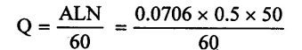
= 0.02941 m3/sec
(4) Power saved is given by
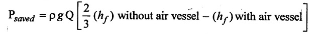
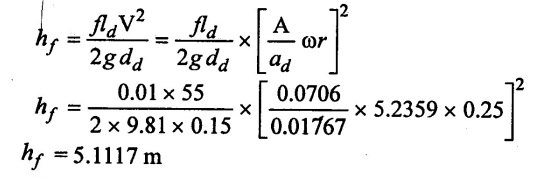
(i) Loss of head due to friction without an air vessel.
(ii) Loss of head due to friction with an air vessel.
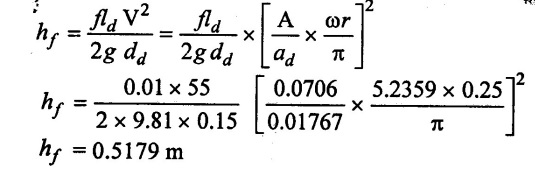
Power Saved
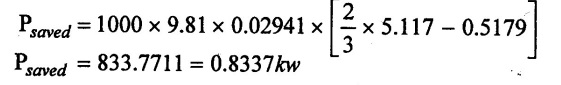
Result:
Power saved Psaved = 0.8337 kw
Example : 35
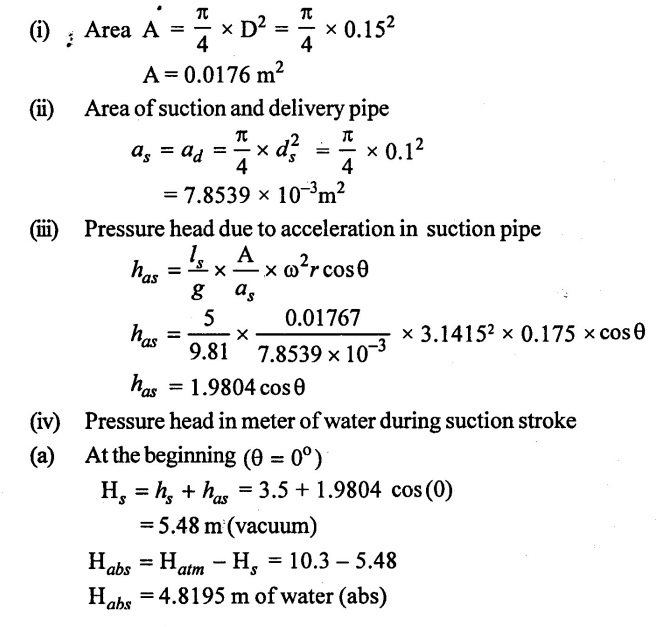
A single acting reciprocating pump has a diameter (piston) of 150mm and stroke length 350mm. The centre of the pump is 3.5m above the water surface in the sump and 22m below the delivery water level. Both the suction and delivery pipes have the same diameter of 100mm and are 5m and 30m long respectively. If the pump is working at 30 rpm determine pressure heads on the piston at the beginning middle and end of the both suction and delivery strokes.
Given data:
Diameted (D) = 150mm = 0.15m
Length (L) = 350mm =0.35m, Pump height surface (hs) = 3.5m
Pump height delivery leves (hd) = 22m
Suction pipe diameter (ds) = 100mm = 0.1 m [Diameter same for both pipes so ds = dd ]
Suction pipe length (ls ̧) = 5m
Delivery pipe length (ld ̧) = 30m
Speed (N) = 30 rpm
To find:
Pressure head for begining, middle and of both suction and delivery stroke.
Solution:
(1) Calculate the pressure head at the beginning middle and the end of the suction stroke
(b) At the middle (θ = 90°)
Hs = hs + has = 3.5 + 1.9804 cos (90)
= 3.5 m (vacuum)
Habs - Hatm - Hs = 10.3 – 3.5
Habs = 6.8 m of water (abs)
(c) At the end (θ = 180°)
Hs = hs + has = 3.5+ 1.9804 cos (180)
= 1.5196 (vacuum)
Habs - Hatm - Hs = 10.3 - 1.5196
Habs = 8.7804 m of water (abs)
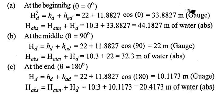
(2) Calculate the pressure head at the beginning middle and end of the delivery stroke
(i) Pressure head due to acceleration in delivery pipe
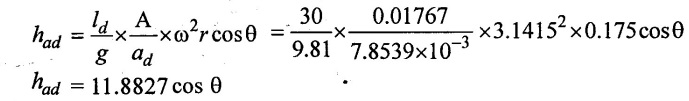
(ii) Pressure head in meter of water during delivery stroke
Result:
(i) Suction stroke
Absolute pressure head begining Habs = 4.8195 m of water
Middle Habs = 6.8 m of water
End Habs = 8.7804 m of water
(ii) Delivery stroke
Absolute pressure head at beginning Habs = 44.1827 m of water
Middle Habs = 32.3 m of water
End Habs = 20.4173 m of water
Example : 36
Determine the maximum speed in rpm at which a single acting reciprocating pump without an air vessel of the following details can be operated without causing separation at any stage during the operation of the pump. Compute the discharge at this speed. The fluid is water. Diameter of plunger 15 cm, stroke = 22.5 cm, suction pipe diameter 10cm, length 50cm, static suction head = 4, static delivery head 25 m atmospheric pressure = 101 kpa and vapour pressure of water = 25.5 kpa.
Given data:
Diameter D = 15 cm=0.15 m
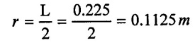
Length L = 22.5 = 0.225m
Suction pipe diameter ds = 10cm = 0.1 m
Suction pipe length (ls) = 50m
Static suction head (hs) = 4 m
Static delivery head (hd) = 25 m
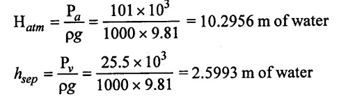
Atmospheric pressure Pa = 101 kpa = 101 × 103N/m2
Pv = 25.5 kpa = 25.5 × 10³ N/m2
To find:
(i) Q and N when air vessel is not fitted
Solution:
(iii) Pressure head due to acceleration is
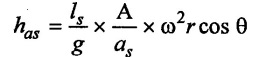
The separation will occur at the begining of the suction stroke so θ = 0°
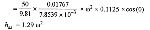
(iv) The pressure head in the cylinder at the beginning of suctionstroke
Hs = hs + has
= 4 + 1.29 ω2
(v) The limiting condition for no separation
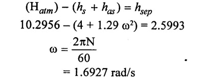
N = 16.1644 rpm
(vi) For single acting cylinder the discharge
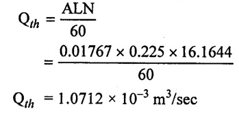
Result:
Qth = 1.0712 × 10⁻³ m3/sec
Speed (N) = 16.1644 rpm
Discharge (Q) = 1.0712 × 10⁻³m3/sec
Example: 37
A single acting reciprocating pump has piston diameter 250mm and stroke length 400mm. The pump takes its supply from 3.2 m below the pump axis through a pipe 10m and 100mm diameter. If seperation occurs at 2.4 m of water absolute. Determine
(i) Speed at which separation may takes place at the beginning of suction stroke.
(ii) The speed of the pump if an air vessel is fitted at the 2.3 m above suction. Take atmospheric pressure head as 10.3 m of water and f = 0.01.
Given data:
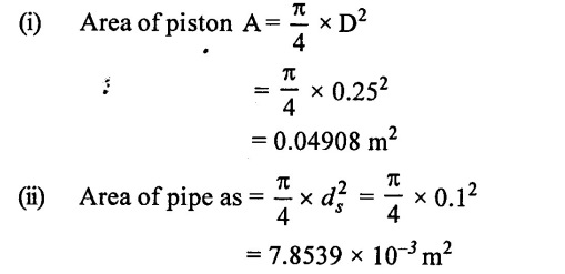
Diameter D = 250mm = 0.25 m
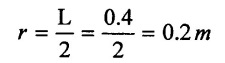
Length L = 0.4m
Suction head (hs) = 3.2 m
Suction length (ls) = 10m
Suction diameter (ds) = 100mm = 0.1 m
Separation occurs = 2.4 m of water
Hatm = 10.3m of water
Co-efficient of friction f = 0.01
To find:
(1) N without air vessel
(2) N with air vessel
Solution:
(1) Calculate the speed at which separation takes place (No air vessel fitted)
(iii) The separation generally tskes places at the beginning of suction stroke (θ = 0). The pressure head due to acceleration.
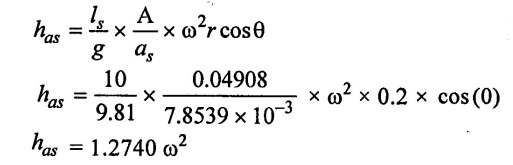
(iv) The pressure head in the cylinder
Hs = hs + has
= 10.3 - (3.2 + 1.2740 ω2)
Hs = 10.3 − (3.2 + 1.2740 ω2)
(v) Limiting condition for no separation
Hatm - (hs + has) = hsep
10.3 − (3.2 + 1.2740 ω2) = 2.4
7.9 = 3.2 + 1.2740 ω2
ω = 1.9207 rad/sec
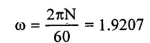
N = 18.3415 rpm
(2) Calculated the speed of pump when air vessel is fitted at suction pipe
(i) Since the air vessel is fitted 2.3 m above the sump level. Therefore ther will be loss of head due to friction for length.
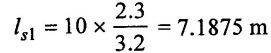
(ii) Acceleration head will be restricted to length
ls2 = (10 - 7.1875) = 2.8125 m
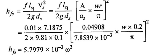
(iii) The pressure head due to acceleration in suction pipe
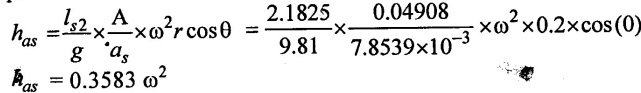
(iv) The loss of head due to friction
(v) Limitation condition for no seperation
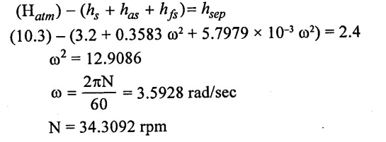
Result:
(1) Speed (N) without air vessel = 18.3415 rpm
(2) Speed (N) with air vessel = 34.3092 rpm.
No comments:
Post a Comment