A Draft tube is a pipe of gradually increasing diameter which connects the exit of runner of a turbine to the tail race.
DRAFT TUBE
A Draft tube is a pipe of gradually increasing diameter which connects the exit of runner of a turbine to the tail race. Therefore, it discharges the water from the runner to tail race. In case of pelton wheel the available head is converted in to kinetic energy before entry to runner buckets and the turbine operate under atmospheric pressure conductions. The velocity of water leaving at turbine exit small therefore the exit of runner is kept above the tail race level. Where as incase of reaction turbine, only the part of available head is converted into kinetic energy before entry to runner and rest of energy is in the form of pressure energy. This pressure energy gradually converted in to runner, thus the velocity leaving the runner is at high velocity. In case runner is kept above the tail race, the K.E. Corresponding to exit velocity utilize the kinetic energy of water at exit of runner, is wasted the draft tube is made on integral part of Francis, kaplan and other reaction turbines in which the draft tube exit is kept below the tail race. The draft tube converts the kinetic energy in to pressure head therefore the function of a draft tube are.
(i) It permits the negative head to be established at outlet of runner, hence it increases the net head available to turbine.
(ii) To convert the kinetic energy of water at exit of runner in to pressure energy so that useful head at runner exit is increases.
1. Types of Draft tubes
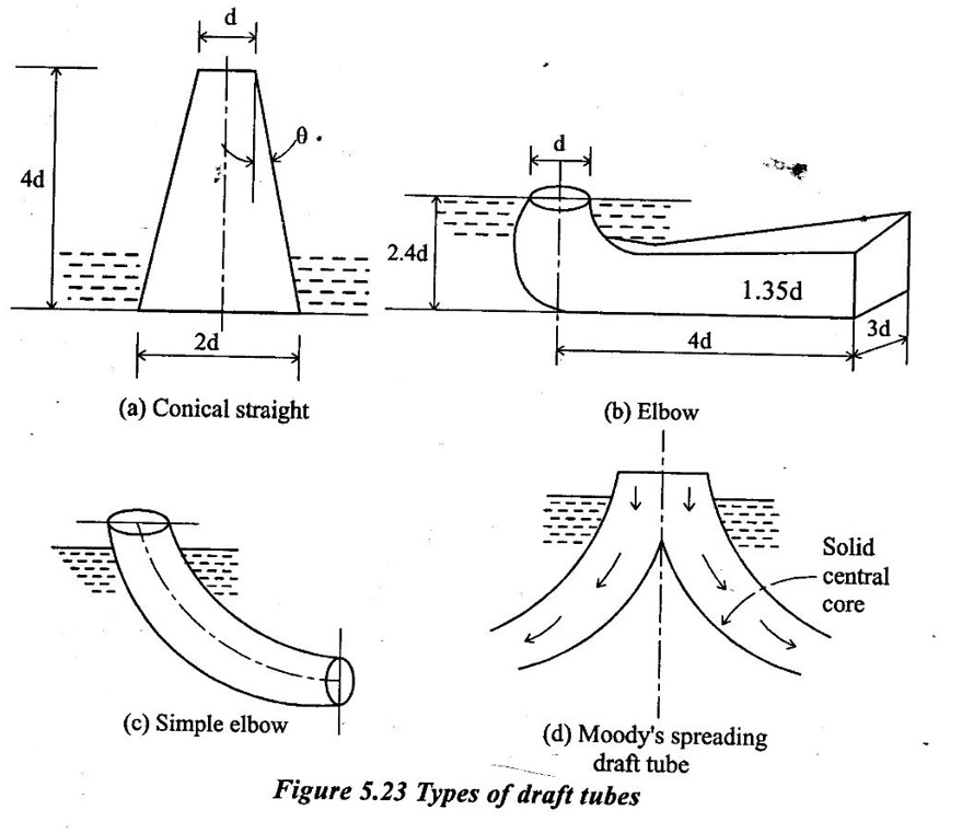
Though there are various types of draft tubes, but the important type of draft tubes are
1. Conical draft tube.
2. Simple elbow draft tube.
3. Elbow draft tube with circular inlet and rectangular outlet.
4. Moody's spreading draft tube.
1. Conical draft tube:
Earlier designs of draft tubes were of conical straight divergent type as shown in figure (a). Taper angle of divergent portion of tube is of great importance. If the taper angle, 20 is large it will cause the separation of flow from the walls of draft tube. In case the taper angle is small, the length of draft tube needed will be long causing higher frictional losses. It may also lead to cavitation problem. Angle θ ranges from 4° to 7° and the proportionate dimensions of the draft tube are shown in given figure. It is fabricated out of mild steel plates. If has an efficiency upto 90% and it is employed for vertical shaft turbines.
2. Simple elbow draft tube:
If has circubr cross-section throughout from inlet to outlet as shown in figure (b) which is turned through 90°. Elbow type draft tubes are used for kaplan turbines. These tubes reduce the depts and cost of excavation.
It is made of concrete with steel lining at inlet to resist cavitation. Due to bend, such draft tubes have an efficiency up to 60%.
3. Elbow draft tube:
Elbow draft tube is shown in fig (c). It is circular in cross section at inlet in its vertical leg which turns in to rectangular cross-section in horizontal portion of tube upto outlet. The horizontal portion of tube is gradually inclined upwards so that the water leaves the tube almost at tail race level.
In this case also, the cost the depth of excavation is reduced. The efficiency of these tubes are in the range of 60% to 80%. It is also made of concrete with steal lining near the runner.
4. Moody's spreading draft tube:
It is similar to conical draft tube as shown in fig (d). It is provided with a solid central core which reduces the whirling action of water. It has an efficiency upto 85% and it is used for vertical shaft turbines having large whirl component at exit of their runner.

No comments:
Post a Comment