Francis turbine is an inward flow reaction turbine which was designed and developed by an American engineer, James B. Francis in 1849.
FRANCIS TURBINE
Francis turbine is an inward flow reaction turbine which was designed and developed by an American engineer, James B. Francis in 1849. In the earlier stages of its development, francis turbine was purely radial flow turbine. In the radial flow turbine, the inlet and outlet velocities of flow of water remains the same in the plane perpendicular to the axis of the runner. The modern version of Francis turbine is mixed flow turbine in which the water enters the runner radially at its outer periphery and leaves it in the axial direction i.e. parallel to the axis of runner.
1. Characteristics of turbine
(i) Both kinetic energy and pressure energy of water exist at inlet to the runner vane.
(ii) Work done is due to partially change in kinetic energy and partially change in pressure energy.
(iii) Both pressure and velocity of water decreases on moving vanes.
(iv) It is a mixed flow reaction turbine.
(v) It is medium speed, medium head and medium discharge turbine.
(vi) This turbine is recommended where medium quantity of water is available plant.
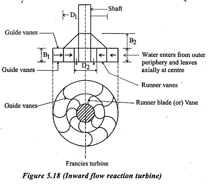
The main components of Francis turbine as shown in figure 5.18.
a) Scroll (or) spiral casing:
The spiral casing is provided on the outer periphery. of the guide vanes. It is a closed passage of gradually reducing cross-sectional area along the direction of flow and cross-sectional area of flow is maximum at inlet and nearly zero at exit. The decrease in area is in proportional to the decreasing volume of water to be handled and ensures that the constant velocity of water is supplied to all the guide vanes at same time. The casing is made of concrete, rolled or plate steel and cast steel.
b) Guide wheel and Guide vanes
A series of air foil shaped vanes, called the guide vanes or wicket gates are mounted on the guide wheel between the spiral casing and the runner. Guide vanes perform two functions. Firstly they direct the water from casing to the runner vanes at an angle appropriate to the design. Secondly, they act as nozzle, the part of pressure energy converted into kinetic energy when water passes through guide vanes. Each guide vane can swing about its own axis and helps to bring a change in the flow area between two consecutive guide vanes. This regulates the flow to the runner according to load variation on the turbine. The movement of the guide wheel is regulated by a governing mechanism.
c) Runner and runner blades
The runner is the most important circulate rotary part of a water turbine. It consists of a series of curved blades (or) vanes fixed on its periphery in such a manner that the water enters radially in to runner and exit axially without shock. The driving force on the runner is both due to impulse (change in kinetic energy) and reaction (change in pressure energy). The runner is made of cast iron, cast steel, stainless steel and non-ferrous.
d) Draft tube
A draft tube is a gradually increasing cross sectional area which is connect the exit of turbine and tail race. In the reaction turbine, as the flow leaves the runner it possesses a considerably large amount of kinetic energy with this kinetic energy, flow enters the draft tube.
The function of the draft tube is to transform a large part of kinetic energy of flow into the pressure energy. The water finally rejected into the tail race where its kinetic energy is reduced upto a large extent by the draft tube. This decreases in kinetic energy increases the working head (or) pressure energy.
e) Governing mechanism
The governing mechanism changes the position of guide blades to affect a variation in the water flow rate in the wake of changing load conditions on the turbine. The system consists of a centrifugal governing mechanism, linkages, servo motor with its oil pressures governor and the guide wheel when the load changes, the governing mechanism rotates all the guide blades about their axes through the same at all the passage between any two consecutive guide vanes. The penstock pipe feeding the turbine is often fitted with a relief valve, also known as the pressure regulator. when the guide vanes are suddenly closed, the relief valve opens and diverts the water direct to tailrace. The simultaneous operation of guide vanes and relief valve is termed as double regulation.
f) Penstock
It is a large sized conduit which conveys water from the upstream of the dam to the turbine runner. Because of the large volume of water flow, size of the penstock required for a Francis turbine is large than that of a pelton wheel. The penstock is in variably made of steel and is imbedded inside the dam. Trash tacks are provided at inlet of the penstock in order to obstruct the entry of debries and other foreign matter.
2. Working of Francis turbine
The water from the reservoir is carried to the turbine through penstocks and enters the scroll casing. The casing distributes water evenly around the circum ference of the turbine runner. From the scroll casing, water passes through the stay ring. This ring directs water to the guide vanes. These guide vanes regulate the quantity of water supplied to the runner. The air foil shape of the guide vanes allow the water of flow smoothly without shock. The water enters the runner with a low velocity and considerable pressure. As the water flows through the runner, the direction of flow of water is changed from axial to radial. The pressure energy is gradually converted in to kinetic energy and the runner is rotated at high speed. This torque is transmitted to the generator which is coupled to the runner shaft. After passing through the runner, water enters the tail race through a draft tube.
3. Efficiency of Francis turbine
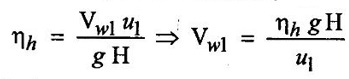
1. Hydraulic efficiency (ηh)
Hydraulic efficiency is the ratio of power developed by the runner to the power available with the water at the inlet of turbine.
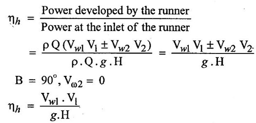
The hydraulic efficiency of Francis turbine varies from 85 to 90%.
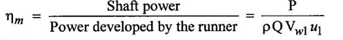
2. Mechanical efficiency
It is defined as the ratio of shaft power to power developed by the Runner. It takes into account the power loss due to friction
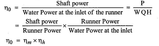
3. Overall efficiency
It is the ratio of the shaft power to the power of water at the inlet of the runner. The overall efficiency varies from 80 to 90 percent
4. Design aspects of Francis turbine
1. Ratio of width to diameter (B/D)
The ratio of width (B1) to the diameter of the wheel (D1) at inlet is represented by n
η = B1 / D1
The value of n varies from 0.10 to 0.45
2. Flow ratio (kf)
Flow ratio is the ratio of the velocity of flow at inlet to the theoretical jet velocity.
Flow ratio, 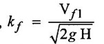
The value of (kf) varies from 0.15 to 0.30
3. Speed ratio (ku)
Speed ratio (ku) =
The value of of (ku) ranges from 0.6 to 0.9
5. Design of Francis turbine
This turbine is generally designed on the basis of desired (i) Power (P) (ii) speed (N) and (iii) head, (H). In designing process, it is required to determine (i) size of runner and (ii) vane angles.
The design of the Francis turbine runner is carried out as follows.
1. Assume suitable values of η0, ηH, Kƒ and Ku.
2. Determine the required discharged (Q) from the relation, P = η0 × WQH
3. Obtain the velocity of flow from the discharge and flow area.
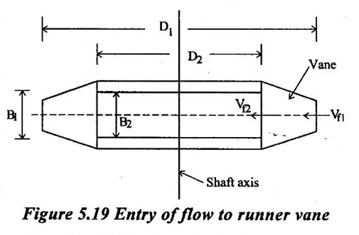
Let B1, D1 and t1 respectively be the width, diameter and thickness of runner vane at inlet as shown in figure 5.19.
(i) Total area at the outer periphery
(i.e at the runner inlet)
A = (π D1 - z) B1 = Kt1 πD1 В1
Z - Number of vanes
Kt - is known as vane thickness factor/coefficient its value is always less than unity usually at the order of 0.95
(ii) Discharge Q = Area of flow × Velocity of flow
= Kt1 πD1 В1 × Vf1
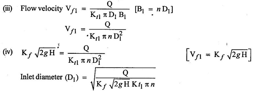
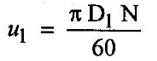
4. Find the rim velocity (tangential velocity) (u1)
5. Find the velocity of whirl at inlet (Vωl)
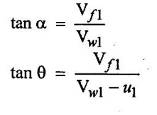
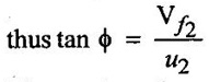
6. Obtain the guide vane angle (α) and the runner vane angle (θ) from the following relations obtained from inlet velocity triangle from figure 5.18.
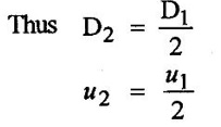
7. Assume runner diameter D2 at the outlet to be approximately one half the diameter at inlet.
8. The velocity of flow at the exit (Vƒ2)
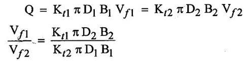
Usually, it is presumed that Vf1 = Vƒ2 and Kt1 = Kt2
that gives B2 = z B1
9. Find the runner vane angle at exit from the velocity outlet triangle, assuming the discharge at the runner exit to the radial (β = 90°)
10. The number of vanes (z) varies from 16 to 24
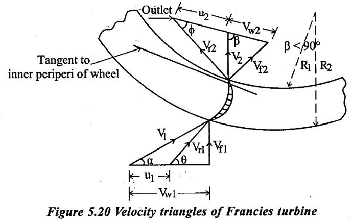
6. Velocity triangles of Francis turbine
In this turbine the blades are fitted radially to the rim of the wheel (or) runner. The velocity triangles of inlet and outlet of the Francis turbine are drawn in the same way as incase of inward flow reaction turbine as shown in figure 5.20.
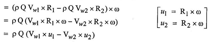
1. Work done per second on the wheel (or) power (p) = Torque × Angular velocity
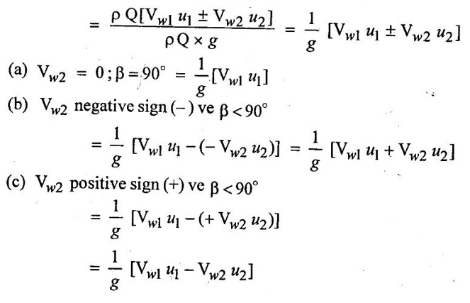
(a) The Vw2 take positive sign (or) negative sign depends on β angle.
When β is an obtuse angle (ie) β > 90° (+) sign
w/sec = ρQ (Vw1 u1 − (+ Vw2) = ρQ (Vw1 u1 - Vw2 u2)
(b) When β is an actue angle (ie) β < 90° (-) sign
w/sec = ρQ (Vw1 u1 − (- Vw2 u2) = ρQ (Vw1 u1 + Vw2 u2)
(c) When β = 90° then Vw2 = 0
w/sec = ρQ (Vw1 × u1)
The general expression for the work done / sec on the wheel
= ρQ (Vw1 u1 ± Vw2 u2)
2. Force exerted in the direction of motion (Fx)
(a) Fx = ρQ (Vw1 + Vw2) β < 90°
(b) Fx = ρQ (Vw1 - Vw2) β > 90°
(c) Fx = ρQ (Vw1) β = 90°
3. Work done/sec/unit weight of water
Advantages:
1. In Francis turbine the variation in the operating head can be more easily controlled.
2. In Francis turbine the ratio of maximum and minimum operating heads can be even two.
3. The operating head can be utilized even when the variation in the tail race water level is relatively large when composed to the total head.
4. The mechanical efficiency of pelton wheel decreases faster which wear than Francis turbine.
5. The size of runner, generator and power house required is small and economical if the Francis turbine is used instead of pelton wheel for same power generation.
Disadvantages:
1. Water which is not clean can cause very rapid wear in high head Francis turbine.
2. The over haul and inspection is much more difficult comparatively.
3. Cavitation is an ever-present danger.
4. The water hammer effect is more troublesome with Francis turbine.
No comments:
Post a Comment