A Roto dynamic is a device either for converting the energy held by a fluid into mechanical energy or vice versa.
THEORY OF TURBO MACHINES
A Roto dynamic is a device either for converting the energy held by a fluid into mechanical energy or vice versa. Fluid machines such as turbines centrifugal pumps. Compressors, fans, hydraulic couplings, and torque converters fall under the category of roto dynamic machines. Roto dynamic machines are called turbo machines and have a rotating element which plays an important role in causing the energy transfer between the fluid and rotating element. The energy transfer may take place from the fluid to the machine as in case of turbines or it may just be the reverse as in case of centrifugal pumps, blowers, Fans & compressors.
Apart from turbo machines, there is a second category of fluid machine known as positive displacement machines in which the fluid is displaced by some moving mechanical element such as a gear system rotating in a closed casing as in case of a reciprocating pump. In positive displacement machines, the static pressure is developed by a displacement action rather than by a velocity or kinetic energy change.
The hydraulic turbine utilize the energy of water and convert it into mechanical energy of the rotating shaft. According to the principle of moment of momentum of water is changed as it flows through the rotating element, there results a torque which rotates the turbine shaft.
The hydraulic turbine constitute an important and essential item of a hydro-electric power plant. The primary function of a hydraulic turbine is to rotate the electric generation the rotation of which produces electrical power.
The water from the storage reservoir (DAM) is allowed to flow through the turbine at pressure. The total energy of flow through the turbine and comes out at the turbine exit, its moment of momentum is considerably reduced. This change in moment of momentum of flow produces a torque on the turbine runner causing it to rotate. The hydraulic energy of water is thus converted into the mechanical energy represented by the rotation of the turbine shaft.
The function of pump is to increase the energy content of the flowing fluid. The increase in fluid energy is made possible by the rotation of the impeller and represents the mechanical energy imported to the pump. This mechanical energy is converted into the hydraulic energy by causing the liquid to flow through the impeller. The pumps are employed when energy of following liquids needs to be increased.
The blowers and compressor are pumps dealing with air or gas. The primary function of a compressor is to increase pressure of air and since high pressure changes are involved density changes must be considered. On the other hand a fan or blower is primarily used for causing the movement of air. In this case, the changes in pressure is quite small. Usually sufficient to overcome the resistance to its flow and so that variation of density is negligible and the fluid may be regarded as compressible.
1. Roto Dynamic Machines Classification.
The variations in nomenclature & design of rotodynamic machine depends upon;
(i) The stages of pressure momentum conversion and classified as Impulse & reaction turbine.
(ii) The path followed by the fluid and classified as Axial, Radial & mixed flow machines.
(iii) The direction of curvature of moving vanes & classified as backward, Radial & forward blade impellers.
2. Various Efficiencies:
Due to losses during the energy transfer, the output of a machine is always less than the input to the machine. Therefore, the efficiency of a machine in general terms can be defined as the ratio of output to input(i.e)
Efficiency η = Output / Input
In hydrodynamic machines, the number of stages are involved in conversion of input energy into useful output with losses at each stage.
There losses are of three types are
(i) Leakage or volumetric losses
(ii) Hydraulic losses
(iii) Mechanical (or) friction losses
Considering these losses, various efficiency of a machine are
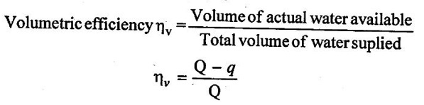
(i) Volumetric Efficiency (ηv)
Consider a turbine operating under head H and it is supplied Q quantity of water per second.
The water power supplied = ρ·Qgh
However, some discharge, q would be lost in leakages at various places, due to this leakage some water power will not be available to produce useful work.
⸫ Water power lost = ρ·Q·g·h
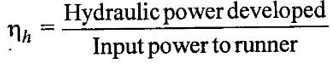
(ii) Hydraulic Efficiency (ηh)
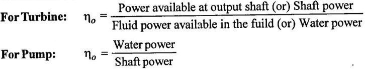
For turbines:
The hydraulic losses are due to liquid friction and local resistances in a machine. Based on this, the hydraulic efficiency is defined as the ratio of hydraulic power developed by the turbine to the input power to runner.
For pumps:
In case of pumps, hydraulic losses will decrease the head developed by impeller called manometric head Hm.
The ratio of manometric head developed to the actual head. Head (H) supplied to machine corresponding to hydraulic power supplied to impeller.
If ΔHm is head lost in hydraulic losses, then
H = Hm + ΔHm
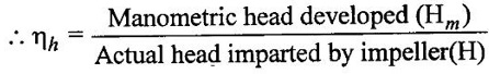
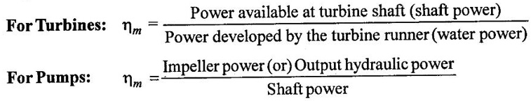
(iii) Mechanical Efficiency (ηm):
The mechanical losses account of various friction losses between various mating parts of a machine and the viscous friction. Based on mechanical losses, the mechanical efficiency can be defined as follows,
(iv) Overall Efficiency (ηo)
It related between the fluid input and fluid output of machine by taking into account all types of losses in a machine. There fore,
Overall efficiency in general, can also be written as,
ηo = ηv × ηh × ηm
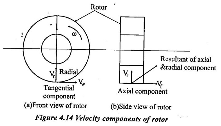
3. Velocity Components of Rotor
When the fluid flows in a roto dynamic machine at an absolute velocity V, it will have three components in three mutually perpendicular directions as shown in figure 4.14. There are
(i) Axial Component. (Vƒ)
It acts along the axis of rotor. The rate of change of momentum due to axial component is responsible to develop axial force which is taken care of by the radial thrust bearings and it is finally transferred to casing.
(ii) Radial Component. (Vr)
It acts along direction of rotor. The rate of change of momentum in radial velocity causes radial force which is taken care of by journal bearings.
(iii) Tangential (or) Whirl Component. (Vw)
It acts along the tangential direction of rotor.
1) Transportation of fluid:
The resultant of radial and axial components of the fluid velocity is called meridonial velocity (or) velocity of flow. This velocity is responsible for flow of fluid through the machine. It plays no role in transfer of energy between the fluid & machine.
Thus, the transportation of fluid through the machine is the responsibility of radial & axial components of velocity.
2) Transmission of force & moment of momentum (angular momentum)
Tangential component of velocity Vw is responsible for transmission of power.
Product of mass flow rate (m) and tangential component of velocity of fluid produces a momentum in tangential direction to the rotor.
The moment of momentum about the axis of rotor gives rise to angular moment producing torque. This torque cause the rotor to rotate, thus produces power.
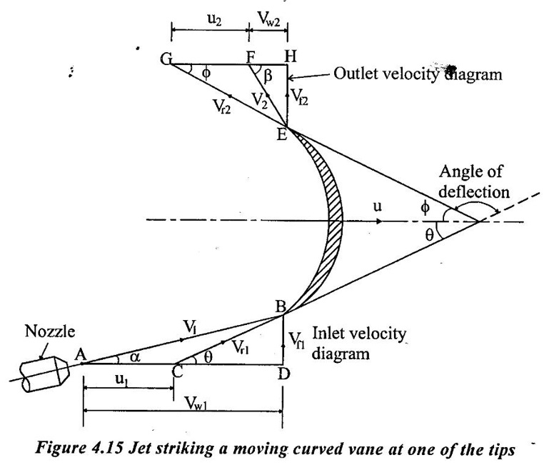
4. Velocity Triangles of rotor:
Consider a jet of water issuing from a nozzle and strikes a moving curved plate (vane) tangentially at one of its tip. The jet strikes the vane tangentially, hence the loss of energy due so impact of jet is zero.
The figure 4.15 shows an unsymmetrical moving curved plate on which jet of water strikes tangentially. We know that, when the plate is moving, the striking velocity is the relative velocity of the jet. It is given as vr = v - u.
Let,
V1 = Absolute velocity of the jet at inlet
u = Velocity of the plate or vane u1 = u2
Vr1 = Relative velocity of jet and vane at inlet
V2 = Absolute velocity of the jet at outlet
Vr2 = Relative velocity of jet and vane at outlet
α = Angle between the direction of jet and motion of plate or guide blade angle or exit angle of nozzle.
θ = Angle made by Vr1 with the motion of plate or vane angle at inlet (or) inlet angle.
β = Angle made by V2 with the motion of plate or leaving angle of jet.
ϕ = Angle made by Vr2 with the motion of plate or vane angle at outlet or exit angle.
From figure 4.15 Vw is called as velocity of whirl or tangential velocity. It is the x- component of absolute velocity.
Vw1 =V1 cosα = Velocity of whirl at inlet.
V w2 = V2 cosβ = Velocity of whirl at outlet.
From figure 4.15 Vf iş called as velocity of flow it is the y-component of absolute velocity.
Vƒ1 = V1 sinα = Velocity of flow at inlet
Vƒ2 =V2 sinβ = Velocity of flow at outlet.
The whirl component of velocity (Vw) is responsible for producing the driving force where as the flow component of velocity (Vf) is responsible for flow of water. In the figure 4.15 ΔABD and ΔEGH represents the inlet and outlet velocity diagrams.
From Inlet Velocity Diagrame (Δ ABD):
To draw inlet velocity diagram consider any point A and draw a line AB of magnitude V1 and angle α with horizontal.
After that, draw a horizontal line AC of magnitude u1 = u and join CB. Now, line CB represents the relative velocity of jet at inlet (Vr1).
As the loss of energy due to impact is zero, the line CB must be tangential to the vane. Finally, draw a vertical line through point B and extend horizontal line AC. The point of intersection is marked as D.
The line AD and BD represents Vw1 & Vf1 respectively and ∠BCD represents angle θ.
From outlet velocity diagram (Δ EGH):
During the flow of water on the vane it is assumed that the vane is smooth. Hence, the loss of energy due to frction will be zero.
It means, the water enters the surface of the vane with relative velocity Vr1 and comes out of the vane with relative velocity Vr2. As there is no friction, Vr1 = Vr2.
Also the relative velocity of the jet at outlet (Vr2) is tangential to the vane at outlet.
To draw outlet velocity diagram, draw line EG in the tangential direction of vane at outlet which represents Vr2.
After that, draw a horizontal line GF of magnitude u2 = u and join EF.
Now, line EF represents the abosolute velocity of jet at outlet in mangitude and direction (angle ẞ).
Finally, draw a vertical line through point E and extend horizontal line GF. The point of intersection is marked as H.
The line FH and EH represents Vw2 and Vf2 respectively and ∠EFH represents angle β.
In this case, the mass flow rate of water striking the vane/sec (m) = ρA Vr1
The force wxcerted by the jet in the direction of motion is given as,
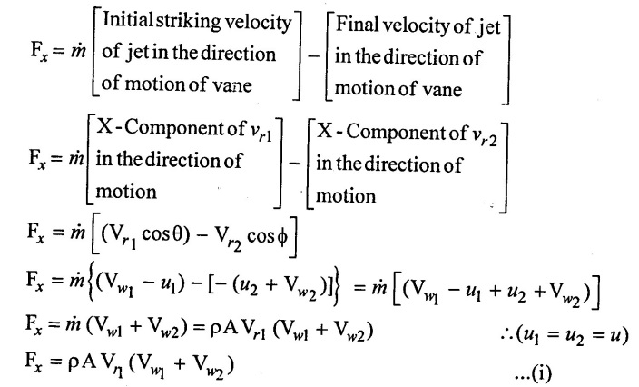
The above equation (i) is applicable only when angle β is less than 90° (β < 90°).
Refer figure 4.16 a.
From 4.16 b. It is clear that if angle β is 90° then Vw2 = 0. At that time, the above equation (i) becomes.
Fx = ρAVr1 (Vw1) ...(ii)
Similarly, if angle β is grater than 90° (β > 90°) then the above equation (i) becomes,
Fx = ρAVr1 (Vw1 -Vw2) ...(iii)

There fore, the general equation of force Fx is
Fx = m (Vw1 ± Vw2) = ρA(Vw1 ± Vw2) ...(iv)
Positive sign is considered when β < 90o
Negative sign is considered when β > 90°
1. Workdone:
The workdone per second (or) power (P) = Fx × u
= ρ A Vr1 (Vw1 ± Vw2) × u N − m / sec ...(v)
The workdone per second per unit weight of water striking per second is,
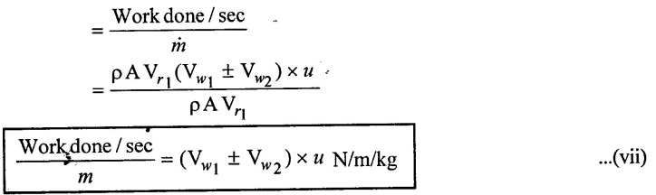
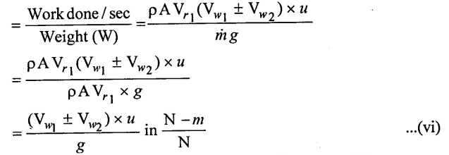 Similarly the work done per second per unit mass of water striking per second is,
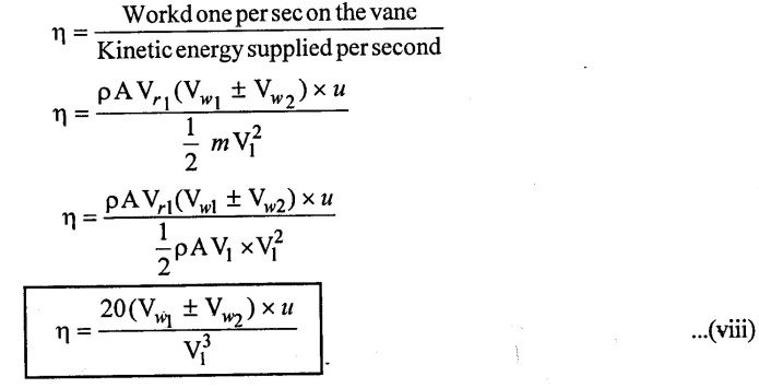
 2. Efficiency of Jet (η):
We know that, the efficiency of a jet or system is defined as the ratio of work done per second on the vane to the kinetic energy supplied by the jet per second.
It is given as,
No comments:
Post a Comment