A centrifugal pump is a rotodynamic pump which has a rotating element called an 'impeller' As the liquid passes through the impeller, it angular momentum change due to which the pressure energy of liquid is converted into potential energy, as the liquid is lifted from a lower level to a higher level.
CENTRIFUGAL PUMP
A centrifugal pump is a rotodynamic pump which has a rotating element called an 'impeller' As the liquid passes through the impeller, it angular momentum change due to which the pressure energy of liquid is converted into potential energy, as the liquid is lifted from a lower level to a higher level. Thus the basic principle of a centrifugal pump on which the pump acts, is that when the mass of liquid is made rotate by the impeller, the liquid is thrown away from the centre of rotation and the centrifugal head is impressed, which helps the liquid to rise to a higher level. Since the liquid is delivered at higher level by the centrifugal head (or) force impressed on it, this pump is commonly called a centrifugal pump is just the reverse of that of a radially in ward flow reaction turbine.
1. Characteristics of Centrifugal Pump
(i) A centrifugal pump is named so, because the energy added by the impeller to liquid is largely due to centrifugal effects.
(ii) It is also called a roto dynamic pump because mechanical energy is converted into hydraulic energy by means of rotating element (impeller).
(iii) It is used for high discharge and low head.
(iv) It occupied less floor space and less running and maintenance cost. Installation is easy and cheap.
(v) Priming is necessary in centrifugal pump.
2. Classifications of Centrifugal Pump
(i) According to working head
(a) Low head (up to 15m)
(b) Medium head (15 m to 45 m)
(c) High head (above 45 m)
(ii) According to casing.
(a) Volute casing
(b) Vortex (or) whirl pool casing
(c) Diffuser casing (or) turbine pump.
(iii) According to the number of entrances to the impeller.
(a) Single suction pump
(b) Double suction pump.
(iv) According to impeller
(a) Closed impeller
(b) Semi-open impeller
(c) Open ompeller
(v) According to number of stage
(a) Single stage centrifugal pump
(b) Multistage centrifugal pump
(vi) According to disposition of the shaft.
(a) Horizontal pump
(b) Vertical pump
(vii) According to shape of the vanes.
(a) Curved forward vanes
(b) Radial vanes
(c) Curved backward vanes
(viii) According to specific speed.
(a) Low specific speed.
(b) Medium specific speed
(c) High specific speed.
3. Main components of centrifugal pump
✓ Casing
✓ Impeller
✓ Suction pipe
✓ Delivery pipe
✓ Other small accessories
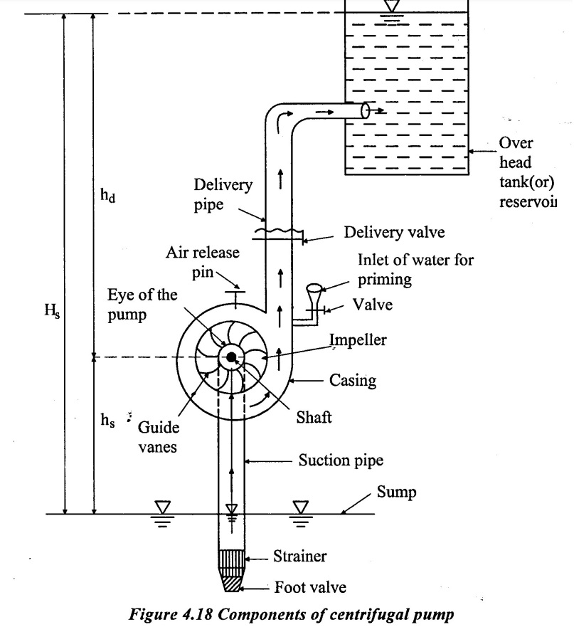
(i) Casing
The cover in which the impeller is enclosed which is called as casing of the pump. The casing is made air tight and water tight to prevent leakage of air into the casing and leakage of water from the casing. It is provided with two openings, one for the suction and the other for the delivery of the liquid handled by the pump. The following purposes one served by casing of centrifugal pump.
(i) Transfer of a part of the kinetic energy of velocity head into pressure energy of pressure head. At outlet of the impeller, there is high kinetic energy and low pressure energy but only pressure energy is responsible to raise the liquid at higher level. Thus it is necessary to increase the pressure energy and decrease the kinetic energy in the casing. The casing act as diffuser.
(ii) Give uniform flow of the liquid coming out of the impeller. Because the mass flow rate of liquid increase from to delivery pipe and cross section area also increases uniformly from to the delivery pipe.
(iii) Increase efficiency of the pump(i.e) increase the head.
(ii) Impeller:
The rotating part of a centrifugal pump is called impeller. It is the main part to raise liquid from a lower to higher level by creating the required pressure with the help of centrifugal action. Whirling motion is imparted to the liquid by means of backward curved vanes provided on the impeller. The impeller is mounted on a shaft which is coupled to the shaft of an electric motor. The function of the impeller is to convert the mechanical energy obtained from electric motor into hydraulic energy. (i.e) (Pressure energy & kinetic energy of water)
(iii) Suction Pipe
The pipe connecting the eye of the impeller to water in sump is called suction pipe. This has to be straight, so that pump can continuously lift the water with suction created by the impeller at pump inlet. At lower end, suction pipe is provided with
(i) Strainer to prevent the entry of any debris along with water into suction pipe.
(ii) Non-return (or) foot value to prevent draining out of water from the suction pipe when the impeller is non-functioning.
(iv) Delivery Pipe
The pipe connecting the outlet of the pump to any height where water is discharged (or) delivered for storage purpose is called delivery pipe. The storage reservoir (or) tank is called over head tank.
(v) Other small accessories:
In addition to the above main components, a centrifugal pump requires some accessories like an inlet valve for water to the pump and an air released valve for priming specially for a small centrifugal pump. A large centrifugal pump has been primed by the casing and suction pipe with the aid of an air pump (or) stream ejector.
Working
Priming is the first step for operating a centrifugal pump. Priming is the operation to fill the suction pipe, pump and a portion delivery with water so that no portion of the suction pipe (or) pump is left with any air (or) vapors pocket. This is normally done by pouring water through the inlet and reversing air by opening the air release pin as shown in figure 4.18. It has been observed that even the presence of a small air pocket with in the pump may prevent the delivery of water. After priming, while the delivery value is kept closed, the pump is started by the electric motor to rotate the impeller. The rotation of the impeller in the casing with full water produces a force vortex which crates a centrifugal head on the liquid. When the centrifugal head is impressed, the delivery valve is opened and the liquid is allowed to flow in an outward radial direction, there by leaving the vanes of the impeller at the outer circumference of the impeller with high velocity and pressure thus the liquid to enter the delivery pipe. A partial vacuum is created at the eye of the impeller which causes the water from the sump at atmospheric pressure to through the suction pipe to the eye. As long as the pump is on, the flow of water from the sump to the delivery head continuously.
4. Types of casing
The casing should be designed in such a manner, so that least amount of energy is lost in eddies formation during transition from kinetic energy to pressure energy. Three types of casing used in a centrifugal pump are,
(i) Volute casing
(ii) Vortex (or) whirlpool casing
(iii) Diffuser casing (or) Turbine pump.
1. Volute gasing
In volute casting type of centrifugal pump the impeller is surrounded by the spiral casing. This casing is such shaped that its - cross section area gradually increases from the tongue to the delivery pipe as shown in figure 4.19.
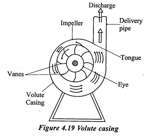
More area is provided to accommodate increased quantity of water as the water moves to wards the delivery pipe. The kinetic energy of the liquid leaving the impeller is reduced in the volute casing. By passing the liquid through gradually in creasing cross- sectional area of the volute casing, a part of its kinetic energy gets transferred into the pressure energy. The impact of the high velocity water leaving the impeller on the slowly moving water in the volute chamber results shock losses. Thus, the efficiency of conversion of the kinetic energy into the pressure energy is very loss.
2. Vortex (or) whirpool casing
This is the improvement on volute casing. In this type of casing, an annular space known as vortex (or) whirlpool chamber is provided between the impeller and volute casing as shown in figure 4.20.
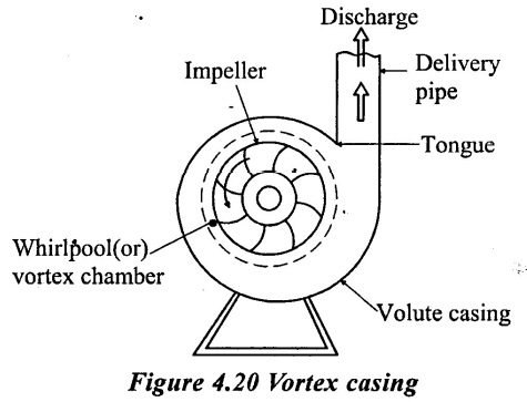
Thus the liquid from the impeller has first to pass through the vortex chamber in which it follow free vortex motion. Since free vortex velocity of flow. Whirl varies inversely as its radial from the centre, velocity of flow of liquid as it passes through the vortex chamber reduces. Thus reduction in velocity, increases the pressure of liquid leaving the vortex chamber liquid then passes through the volute casing. In this process, the loss of energy in eddies being reduced because more kinetic energy of the liquid is converted into pressure energy. Thus vortex casing is more efficient then a volute casing.
3. Diffuser casing (or) Turbine pump
In this casing, the guide vanes are arranged at the outlet of the impeller. The guide vanes are fixed with the ring are shaped in such a manner that they provide gradually enlarged passage for the flow of liquid. The liquid coming out of the impeller, enters the guide vanes without shock while flowing through the increasing area in the guide vanes, kinetic energy of liquid get transferred into pressure energy.
A diffuser casing is more efficient because of gradual reduction of velocity through the guide vanes. So less energy is wasted in eddies. A well designed diffuser casing is capable of transferring 75% of the kinetic energy at the impeller outlet into pressure energy.
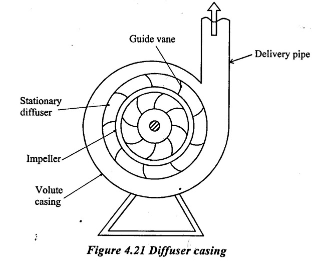
The pumps having diffuser casing are known as diffuser pumps or guide vane pumps. There are also known as 'turbine pumps' because inward flow reaction turbine has similar construction. These pumps are costly and used only for developing high head (61m or more). The diffuser pumps are mostly used as vertical shaft and very suitable for installation in deep well and mines.
5. Types of Impeller
The following are the three types of impeller commonly used in a centrifugal pump.
✓ Closed impeller
✓ Open impeller
✓ Semi-open impeller
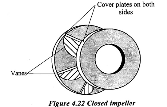
1. Closed impeller.
If the vanes of the impeller are covered with plates on both sides, it is called a closed impeller. This impeller is used in ordinary centrifugal pump which has to handle pure liquid (free from foreign matter or debris Ex, ordinary water, oils, milk and chemical like acids etc.)
 (a) The impeller is made of cast iron if fresh water is to be pumped.
(b) The impeller is made of stainless steel to prevent contamination if milk is to be pumped in milk industry.
(c) The impeller is made of cast steel if the temperature of hot water is more than 122°C.
(d) The impeller is made of stainless steel (or) Gun metal if there is change of corrosion due to chemical impurities in the liquid.
2. Semi-open impeller
If the vanes of the impeller are covered with plate on one side, it is called semi- open impeller as shown in figure 4.23.
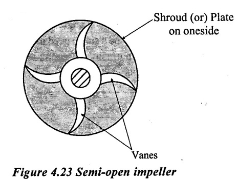
This type of impeller is used for handling highly viscous liquid such as paper pulp, sugar mollasses, sewage water etc, so that it does not get clogged by the viscous liquid. Semi-open impeller has less number of vanes, but the height of the vanes is more than that of closed impeller.
3. Open impeller:
If the vanes of the impeller are without covered plate, it is called open impeller as shown in figure 4.24.
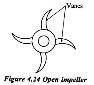
This type of impeller is used for pumping liquids having coarse debris of large size such as mixture of water, sand clay & pebbles. As these impellers are required to perform very rough duty, these are generally, made of forged steel. These impeller has less life, as they have to perform very rough task.
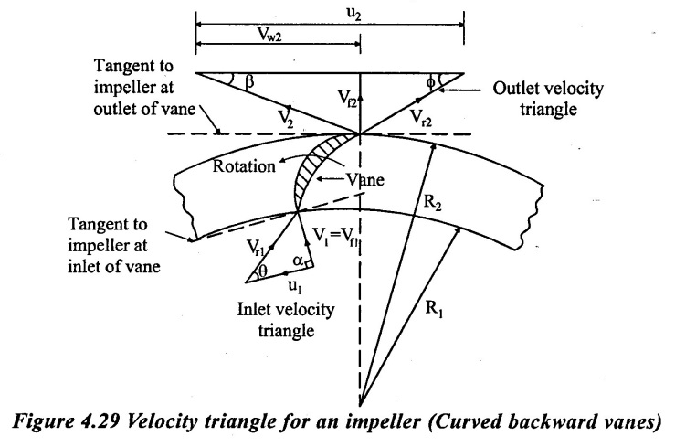
6. Types of shapes of the vanes.
A centrifugal pump has three types according to shape of the vanes are
(i) Curved forward vanes
(ii) Radial vanes
(iii) Curved backward vanes
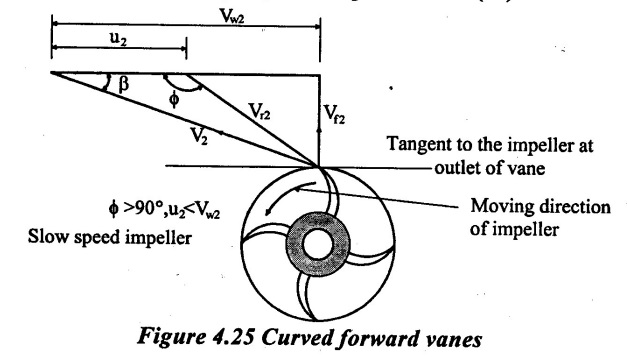
1. Curved forward vanes:
The outlet tip of the vane is curved forward in the direction of rotation of the impeller as shown in figure 4.25. The blade angle at outlet tip, ϕ > 90° and u2 < Vw2. The impeller having such vanes is called a slow speed impeller. This type of the impeller has low efficiency about 75% and is normally not recommend, because of speed reduction mechanism required between the pump shaft to prime mover (i.e) electric motor.
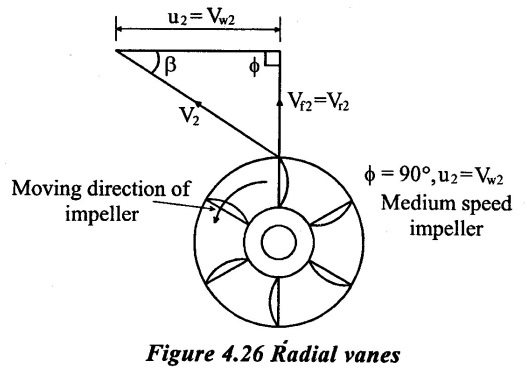
2. Radial vanes:
These vanes have outlet tips in radial direction as shown in figure 4.26. The blade angle at outlet tip, ϕ = 90° and u2 = Vw2. The impeller having such vanes is suitable for medium speed. The efficiency of this type of impeller varies from 80% to 85.
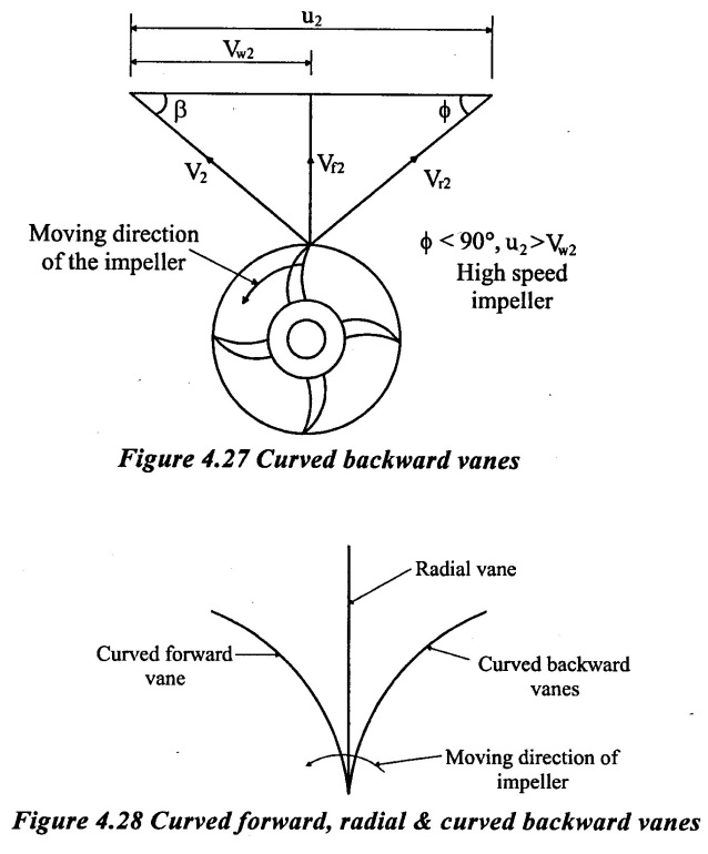
3. Curved backward vanes:
The outlet tip of the vane is curved backward in the direction of rotation of the impeller as shown in figure 4.27. The blade angle at outlet tip, ϕ < 90° and u2 < Vw2. The impeller having such vanes is called a fast speed impeller. The pumps can be coupled directly with the electric motor and no need any speed reduction mechanism. This type of impeller gives highest efficiency 85% to 90%.
7. Work done by the impeller (or centrifugal pump) on liquid:
The liquids enters the impeller at its centre and leaves at its outer periphery.
Assumptions:
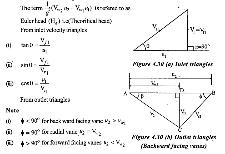
(i) Liquid enters the impeller eye in radial direction, the whirl component Vω1 (of the inlet absolute velocity V1) is zero and flow component Vf equals the absolute velocity f itself i.e., (V1 = Vf 1) and α = 90°
(ii) No energy loss in the impeller due to friction and eddy formation.
(iii) No loss due to shock at entry.
(iv) There is uniform velocity distribution in the narrow passages formed between two adjacent.
Figure 4.29 shows a portion of the impeller of a centrifugal pump with the one vane and the velocity triangles at the inlet and the outlet tips of the vane.
D1 = Diameter of the impeller at inlet (R1 = D1/2)
D2 = Diameter of the impeller at outlet (R2 = D2/2)
ω = Angular velocity 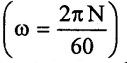
u1 = Tangential velocity of the impeller at inlet.
u2 = Tangential velocity of the impeller at outlet
V1 = Absolute velocity of water at inlet.
Vω1 = Velocity of whirl at inlet.
Vr1 = Relative of whirl at inlet.
Vf1 = Velocity of flow at inlet
α = Angle made by absolute velocity (V1) at inlet with the direction of motion of vane.
θ = Angle made by the relative velocity (Vr1) at inlet with the direction of motion of vane.
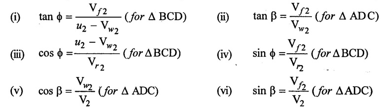
V2, Vω2, Vr2, Vƒ2, β and ϕ are the corresponding values at outlet.
While passing through the impeller, the velocity of whirl changes and there is a change of moment of momentum.
Momentum at the inlet = m × Vw1
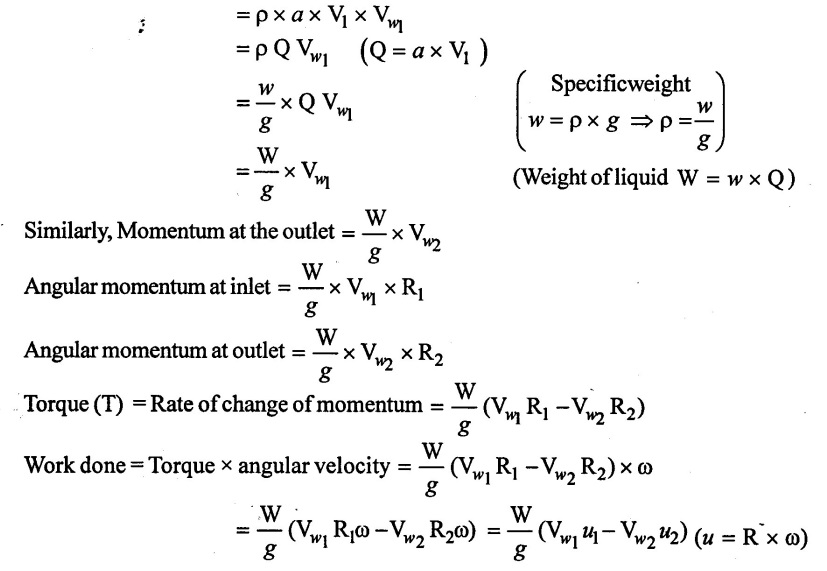
Since the centrifugal is the reverse of the turbine, so the workdone by the impeller on the water/sec.
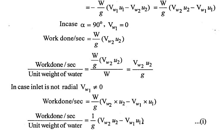
The above equation (i) is know as the Euler momentum equation for the centrifugal pump.
Mostly used backward facing vanes.
8. Head of a Pump
(a) Suction head
It is the vertical distance between liquid levels in the sump and the centre line of the pump. It is denoted by hs. In practically, the value of suction head (hs). 7m to 8m is used to avoid cavitation.
(b) Delivery head
It is the vertical distance between the liquid surface in the over head tank to which the liquid is delivered above the centre line of the pump. It is denoted by hd.
(c) Static head
It is the vertical distance between liquid level in the sump and the over head tank. It is denoted by Hstat
Hstat = hs + hd
(d) Manometric head
The head against which a centrifugal pump has to work is known as the manometric head. It is denoted by Hmano. It can be measured by the following ways.
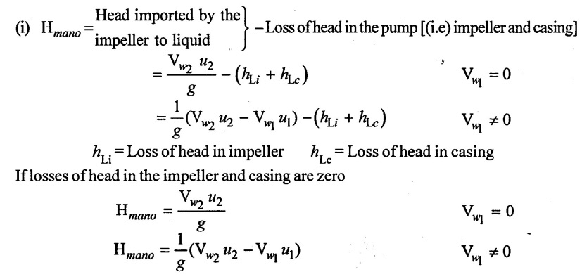
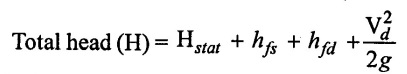
(ii) Hmano = Static head(Hstat) + losses in pipes + Kinetic head of delivery pipe
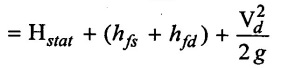
hfs = Frictional head loss in the suction pipe
hfd = Frictional head loss in the delivery pipe
Vd = Velocity of liquid in delivery pipe
(iii) Hmano = Total head at outlet of the pump - Total head at inlet of the pump
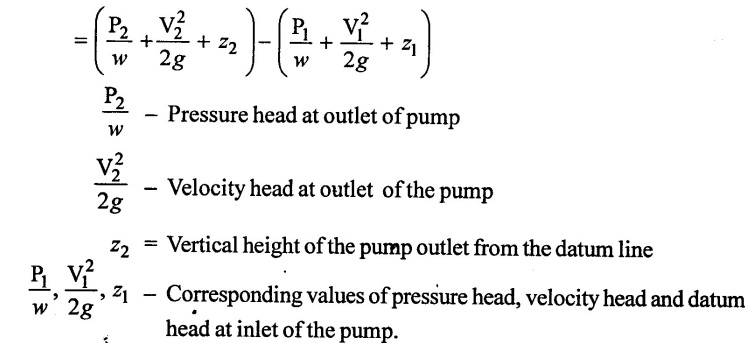
(e) Total head.
It is the total head which has to be developed by a pump to deliver the liquid from the sump into the overhead tank. It is denoted by H.
Loss in the casing and the impeller are not taken into account in the total head. The total head is also known as gross head (or) effective head.
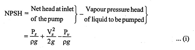
(f) Net positive suction head (NPSH)
It is defined as the difference between net head at inlet of the pump and vapour pressure head of liquid to be pumped.
Apply Bernoulli's equation at inlet of the pump and the sump level.
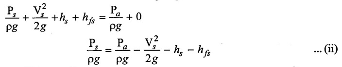 Apply eqn (ii) in eqn (i)
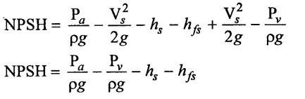
Pa/ρg = Atmospheric pressure head on the liquid surface in the sump.
Pv/ρg = Vapour pressure head of the liquid to be pumped.
hs = Suction pressure head.
hfs = Head loss due to friction in suction pipe
Thus NPSH represent the total suction head at the impeller eye. This much suction head must be created by the impeller. So that the liquid is lifted up from the sump into the impeller through the suction pipe.
It is helped for designing a centrifugal pump and represent the minimum required difference between the suction head and vapour pressure head at given capacity. If the NPSH is insufficient, cavitation may occur, insufficient NPSH may occur due to very high suction head or lift.
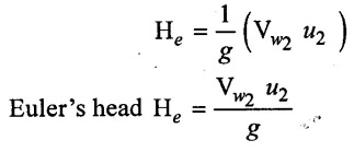
(g) Euler's head
It is defined as the head developed by the impeller. It is denoted by He. Energy supplied by the impeller to the liquid/unit mass.
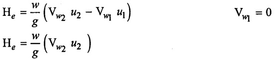
Energy supplied by the impeller to the liquid per unit weight
9. Efficiency of the centrifugal pump
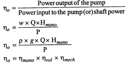
(i) Manometic efficiency (ηmono)
The ratio of the manometric head developed by the pump to the head'imparted by the impeller to the liquid is known as manomtric efficiency.
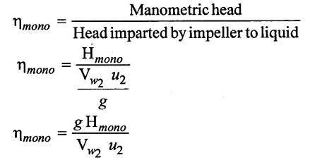
It is also called as hydraulic efficiency.
(ii) Volumetric efficiency (ηvol)
It is defined as the ratio of actual liquid discharge per second from the pump to the total liquid discharge per second passing through the impeller.
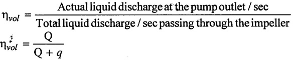 Q - Actual discharge at the pump outlet/sec.
q - Leakage of liquid/sec from the impeller.
Q + q = Total liquid discharge/sec passing through the impeller.
Its values between 98% - 99%.
(iii) Mechanical efficiency (ηmech)
The ratio of the power delivered by the impeller to the liquid to the power input to the pump shaft is known as mechanical efficiency.
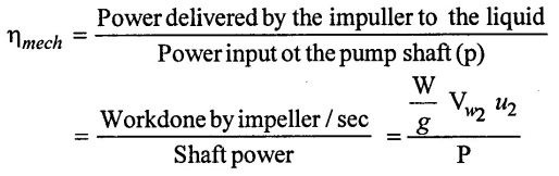
Weight of liquid (W) = w × Q = ρ × g × Q
w = Specific weight of liquid
Q = Discharge of water.
Its value lies between 96% - 98%
(iv) Overall all efficiency (η。)
The ratio of power output of the pump to the power input to the pump is known as overall efficiency (ηo) •
10. Losses of centrifugal pump
Energy losses in centrifugal pumps may be classified as follows.
a) Hydraulic losses
b) Mechanical losses
c) Leakage losses
(1) Hydraulic losses.
(i) Pipe line losses → Major (due to friction) and minor losses in the suction and delivery pipes are called pipe line losses.
(ii) Pump losses → These losses are eddy or shock losses at the entrance and exit of the impeller, frictional losses in the impeller, frictional and eddy losses in the guide vane/diffuser and casing.
(2) Mechanical losses:
These are the losses due to friction of the main bearing and glands, disc friction as the impeller rotates in liquid which fills the clearance space between the impeller and casing.
(3) Leakage losses:
There is always a tendency on the part of liquid to slip back through the clearance between the impeller and the casing due pressure difference at the outlet and inlet of the impeller. (i.e high pressure at outlet of the impeller and low pressure at inlet of the impeller of the centrifugal pump). This liquid carries energy with it which is ultimately wasted and this loss of energy of liquid is known as leakage loss.
11. Cavitation
Cavitation is defined as the phenomenon of formation of vapour bubbles of a flowing liquid in a region. Where the pressure of the liquid falls below its vapour pressure and the sudden collapsing of these vapour bubbles in a region of higher pressure when the vapour bubbles collapse, a very pressure is created. The metallic surfaces, above which these vapour bubbles collapse, is subjected to these high pressures, which cause pitting action on the surface. Thus cavities are formed on the metallic surface and also considerable noise and vibrations are produced.
Cavitation includes formation of vapour bubbles of the flowing liquid and collapsing of the vapour bubbles formation of vapour bubbles of the flowing liquid take place only whenever the pressure in any region falls below vapour pressure. When the pressure of the flowing liquid is less then its vapour pressure, the liquid starts boiling and vapour bubbles are formed. These vapour bubbles are carried along with the flowing liquid to higher pressure zones where these vapours condense and bubbles collapse. Due to sudden collapsing of the bubbles on the metallic surface, high pressure is produced and metallic surfaces are subjected to high local stresses. Thus the surfaces are damaged.
1. Precaution Against Cavitation.
The following precautions should be taken against cavitation
(i) The pressure of the flowing liquid in any part of the hydraulic system should not be allowed to fall below its vapour pressure. If the flowing liquid is water, then the absolute pressure head should not be below 2.m of water.
(ii) The special materials or coatings such as aluminum, bronze and stainless steel, which are cavitation resistant materials, should be used.
2. Effects of cavitation.
(i) The metallic surfaces are damaged and cavities are formed on the surfaces.
(ii) Due to sudden collapse of vapour bubbles, considerable noise and vibrations are produced.
(iii) The efficiency of a turbine decreases due to cavitation. Due to pitting action, the surface of the turbine blades becomes rough and the force exerted by water on the turbine blades decreases. Hence, the work done by water (or) outlet horse power becomes less and thus efficiency decreases.
3. Cavitation in centrifugal pumps
In centrifugal pumps the cavitation may occur at the inlet of the impeller of the pump, or at the suction side of the pumps, where the pressure is considerably reduced. Hence if the pressure at the suction side of the pump drops below the vapour pressure of the liquid then the cavitation may occur. The cavitation in a pump can be noted by a sudden drop in efficiency and head. In order to determine whether cavitation will occur in any portion of the suction side of the pump, the critical value of thoma's cavitation factor (σ) is calculated.
12. Priming
It is defined as the operation in which the-suction pipe, casing of the pump and delivery pipe up to delivery valve is completely filled by liquid to be pumped. A priming in needed only in centrifugal pump. No need of priming if the suction pipe and casing of the pump is already filled with liquid. No need of priming in case of reciprocating, gear, screw, vane pump etc. If there is no priming these will be no discharge when air get partially or completely entered in the casing of the centrifugal pump.
If a centrifugal pump is not running for a long period of time, the water present in the pump casing and suction pipe either flow back to the sump or leaked out and space in casing and suction pipe get filled with air. Now, when the pump start running, the sufficient pressure is not developed by impeller. Since the density of air is far less than the density of water & pressure developed by the impeller directly depends upon density.
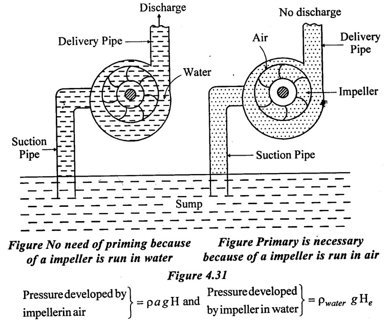
To avoid this difficulty priming in necessary.
A primary of a centrifugal in done by the following three methods.
a) Manual
b) Priming by vacuum
c) Self-priming
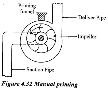
1. Manual priming
(i) Liquid is poured through a funnel into the casing and thus replacing the air as shown in figure 4.32.
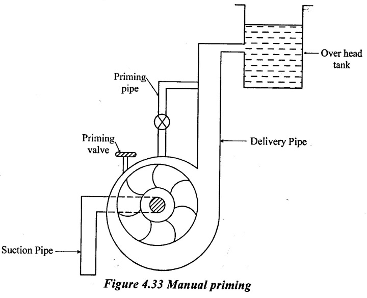
(ii) When the pump is discharging into an overhead tank, then for priming purpose delivery pipe is connected with the casing with priming pipe as shown in figure 4.33. When priming in required, liquid from the overhead tank can be used. The priming valve is provided at the top of the casing to allow air to escape from the casing while doing priming. After priming, priming valve is closed.
 2. Priming by vacuum:
Air or vacuum pump may be provided which can be run by the centrifugal pump shaft. It can be fitted on the suction side of the pump. On starting, the vacuum pump will take out all air from the suction pipe then atmospheric pressure in the sump forces the water to rush into the suction pipe and casing, water starts pouring out of the pump.
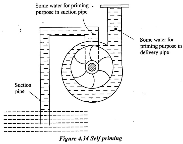
3. Self-priming:
Self-priming means priming is done automatically by the pump. Therefore, self priming centrifugal pumps are very useful. As self-priming devices require large expenses, hence this is used with big size pump only. One of the simplest arrangement of self priming as shown in figure 4.34 in which the suction and delivery pipes are connected at the top of the pump. When the pump comes to rest, it will always have some water for priming purposes in suction pipe and delivery pipe.
13. Performance characteristics curve
Various graphs are plotted for power head and efficiency Vs the discharge.
1. Types of performance characteristics curves.
The performance characteristics curves are broadly divided into following four
categories.
(i) Main characteristics curves
(ii) Operating characteristics curves
(iii) Iso-efficiency (or) Muschel curves
(iv) Constant head and constant discharge curves.
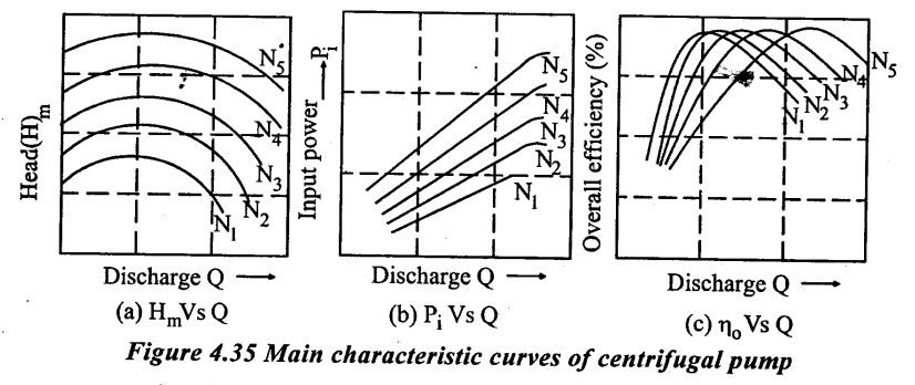
(i) Main characteristics curves.
Main characteristics curves are obtained by test run at constant speed and the discharge is varied by means of delivery valve. At each discharge, the manometric head Hm and input power P are measured and the overall efficiency ηo is calculated.
Test curves are plotted between Hm, Vs Q, PVs Q and ηo Vs Q as shown in figure for that constant speed. The test run is repeated by running the pump at another constant speed. A family of curves will be obtained at various constant speeds N1, N2 as shown in figure.
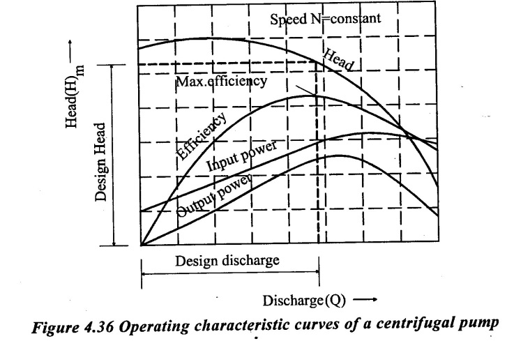
(ii) Operating characteristics curves.
The pumps are designed for maximum efficiency at a given speed called designed speed. There for the pumps are test run at designed speed as provided by the manufacturer of the pump.
The discharge is varied as discussed in case of main characteristics curve and the head and power input one measured. The overall efficiency of the pump is calculated. The performance curve is obtained at design speed are called operating characteristics curve at shown in figure 4.36.
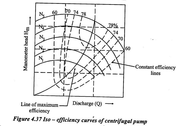
 (iii) Iso-efficiency (or) muschel curves.
Iso-efficiency (i.e) constant efficiency curves are useful in predicting the performance on entire operations and its best performance.
These characteristics curves can be drawn with help of ηo Vs Q and Hm Vs Q curves shown in figure 4.37. The method is as follows.
(i) Draw a horizontal line on ηo Vs Q curve. It represent the constant efficiency line.
(ii) The points at which the constant efficincy line cuts the constant sped lines, the discharges are noted.
(iii) At a given discharge and speed, the Hm is noted from H Vs Q graph.
(iv) These values of Hm and Q at constant efficiency and speed are projected on a graph of Hm Vs Q as shown in figure.
(v) The points corresponding to same overall efficiency are then joined with a smooth curve as shown in figure these curves represent the iso-efficiency curves.
These iso-efficiency curves help to locate the regions. Where the would operate at maximum efficiency.
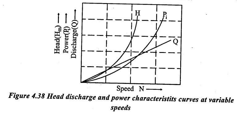
(iv) Constant Head and constant discharge curves:
Often a centrifugal pump is draw required to operate variable speed than the designed speed. There fore it is necessary to the performance curves of a pump at variable speed so that these curves can be used to predict the performance. the procedure is as follows.
The delivery value opening is fixed and kept constant during the test onpump. Then it is operated head Hm discharge Q and power input Pi are measured. The graphs H Vs N, Pi Vs N and Q Vs N can be drawn as shown in figure 4.38.
14. Specific speed of the pump
The specific speed of a centrifugal pump is defined as the sped of a geometrically similar pump which would deliver discharge of one cubic metre per second under a head of one metre. The specific speed of a pump is denoted by Ns.
Discharge Q = area × velocity of flow = л DB × Vƒ
(or)
Q α DBVƒ
Where
D = Diameter of the impeller B = Width of the impeller
But width B is proportional to the diameter of the impeller (i.e) BαD
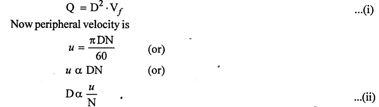
Both tangential velocity of the impeller and flow velocity are proportional manometric head (Hm).
Hence, we have,
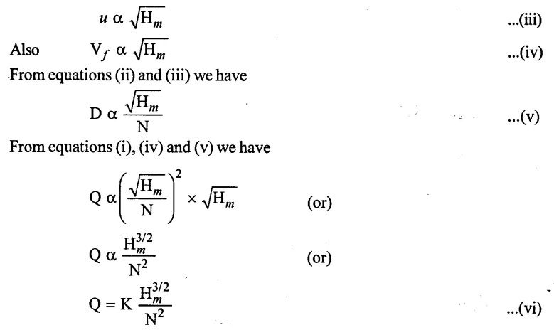
Now as per the definition of specific speed N = Ns when Q = 1 m3 / s and Hm = 1 metre. Putting values in equation (vi) we have
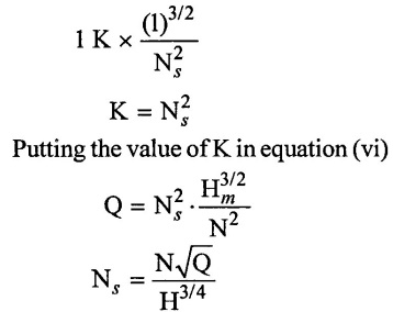
The specific speed is specified in rpm and it is independent of the dimensions of the pump. Specific speed depends upon the shape rather than the size of the pump. All pumps of the same shape have the same value of specific speed. The specific speed for different types of impellers are,
(a) Slow speed radial flow runner -10 to 30
(b) Normal speed radial flow runner - 30 to 50
(c) High speed radial flow runner - 50to 80
(d) Mixed flow runner - 80 to 160
15. Design aspects of centrifugal pump
(i) Speed ratio (ku)
The speed ratio is the ratio of the peripheral speed at the exit (u2) to the jet corresponding to manometric head (Hm)
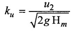
The value of ku various from 0.95 to 1.3.
(ii) Flow ratio (kƒ)
Flow ratio is the ratio of the velocity of the flow at the exit (Vƒ2) to the theoritical velocity of the jet possible with manometric head (Hm).
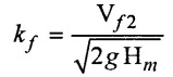
It varies from 0.1 to 0.25
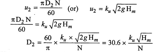
(iii) Diameter of impeller
Diameter can be worked out from manometric head (Hm) and rotational speed (N) as given below.
(i) Outlet diameter of impeller (D2)
(ii) Inlet diameter of impeller
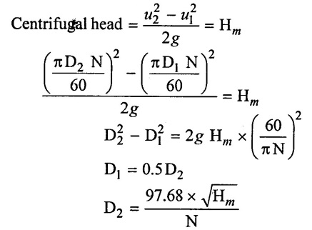
Inside diameter (D1) of an impeller is taken as 1/3 to 2/3 of the outside diameter (D2). The usual value of D1 is taken as half of D2.
(i.e) D1 = 0.5 D2
(iii) Last diameter of impeller
The least diamerter of an impeller can be determined by taking centrifugal head equal to the manometric head.
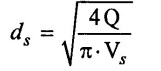
(iv) Diameter of suction pipe (ds)
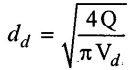
(v) Diameter of delivery pipe
(vi) Discharge (Q)
Q = π D1 B1 × Vƒ1 = лD2 В2 × Vƒ2
16. Minimum speed:
If the pressure rise in the impeller is more than or equal to manometric head (Hm). The centrifugal pump will start delivering water. Otherwise, the pump will not discharge any water, though the impeller is rotating. When impeller is rotating, the water is contact with the impeller is also rotating, this is the case of forced vortex. In case of forced vortex, the centrifugal head or head due to pressure rise in the impeller.
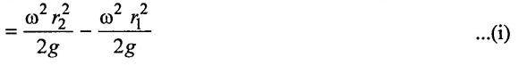
Where
ωr2 = Tangential velocity of impeller at outlet = u2
ωr1 = Tangential velocity of impeller at inlet = u1
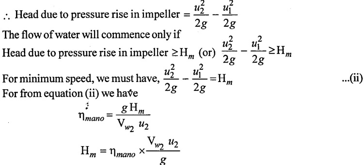 Substituting this value of Hm in equation (ii)
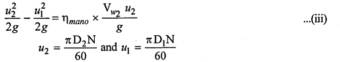
Substituting the values of u2 and u1 in equation (iii)
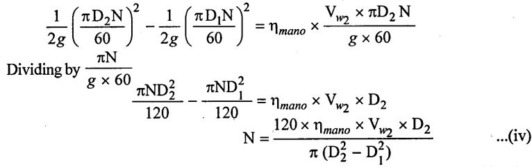
The above equation (iv) gives the maximum starting speed of the centrifugal pump.
17. Applications of centrifugal pump
(i) Irrigation purposes
(ii) Feeding water in boilers
(iii) Used in mine drainages
(iv) Water supply to the towns
(v) Used in refrigeration and air conditioning system.
(vi) Circulation of cooling water through condenses in power plants.
18. Elementary Cascade Theory:
Work is done on a fluid (or) exerted from it by turbomachines, continuously, by the flow through a series of moving vanes. The series of similar blades or vanes are known as cascade.
A simple fixed cascade system of vanes is shown figure 4.39 the velocity vector has been turned through an angle by the presence of the cascade system. A force has been exerted on the fluid, but no work is done
In rotodynamic machines, the cascade of blades is arranged symmetrically around the periphery of a circle. Again, no work is done by the fixed vane system. Consider another series of cascade of blades rotating inside the fixed vane system with a angular velocity 'ω'. The fluid flow on the moving blades should be with minimum disturbance, (i.e.,) in a tangential direction to have an efficient operation of the system.
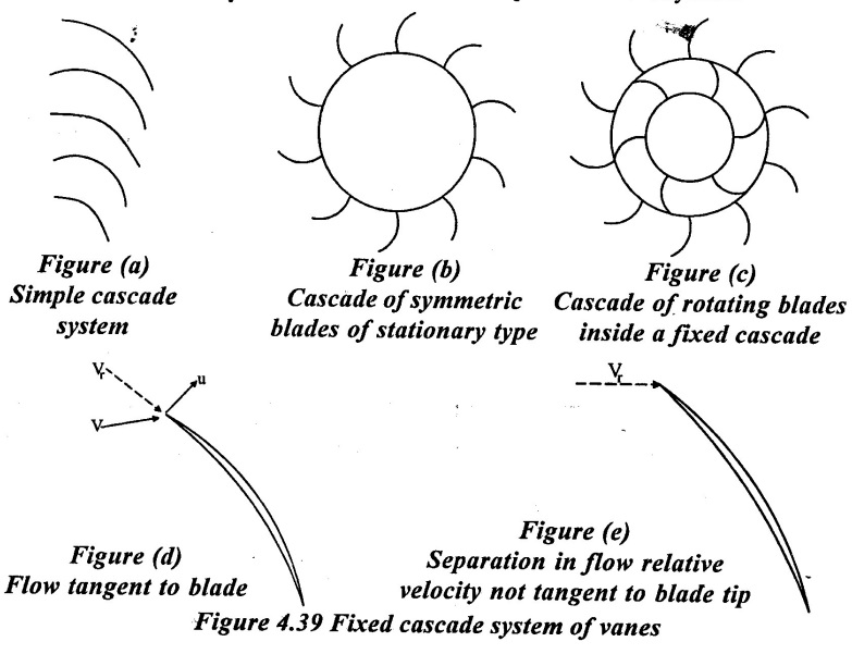 When the relative velocity is not tangent to the blade at entry, separation may occur.
The losses tend to increase rapidly with angle from the tangential and hence the efficiency of the machine will go down.
Also when the approaching relative velocity is tangential to the blades. Separation occurs frequently. This is due to the curvature of the blades as well the expansion of the flow passages. These losses are called as shock or turbulence losses.
When the fluid exits from the moving cascade, its velocity change both in magnitude and direction. This results in change of moment of momentum and hence the fluid either do work on the cascade of having work done on it by the moving cascade.
Turbomachines design requires proper arrangement and shaping of passages and blades for most efficient working. The particular design depends on the purpose of rotodynamic machine, the amount of work done per kg of fluid and the density of the fluid.
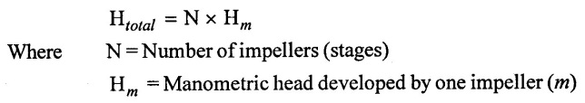
19. Multi-stage centrifugal pumps:
It is not possible to produce very high head with one impeller. This because of the restrictions in the speed of the impeller to avoid cavitation and turbulent losses.
If the head required is very high a multi stage centrifugal pump can be used.
1. Function of Multistage pump
✓ To produce high head
✓ To discharge a large quantity of liquid
To produce a high head, the impellers are connected in series (or on the same shaft), while for discharging large quantity of liquid, the impellers are connected in parallel.
20. Pump in series
For developing a high head, a number of impellers are mounted in series or on the dame shaft as shown in figure 4.40.
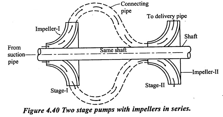
The water from the suction pipe enters the first impeller at inlet and is discharged with an increased pressure at outlet. The discharge from the first impeller with increased pressure passes into the into the inlet of the second impeller with the help of a connecting pipe as shown in figure 4.40. At the output of the second impeller, the pressure of water will be more than the pressure of water at the outlet of the first impeller. Thus if more impellers are mounted on the same shaft, the pressure at the outlet will be increased further. Then the total head produced is
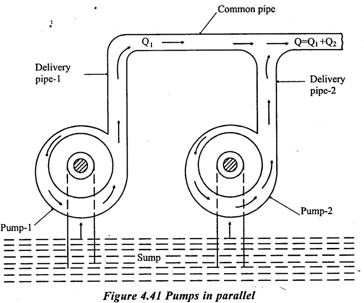
21. Pumps in Parallel
When the discharge required is very high at a relative low head, it may not be possible for a pump to deliver the required discharge. For very high discharges, two (or) more pumps are arranged in parallel. This is done by mounting one impeller (pump). On each shaft separately. They work separately and lifts water from a common sump. They deliver water to a common delivery pipe as shown in figure 4.41.
 Let
Let
Q1 = Discharge from the first pump.
Q2 = Discharge from the second pump
N = Total number of identical pumps arranged in parallel
If the discharge from each pump is equal, then the
Total discharge Q = Q1 + Q2 + Q3 ...... + Qn
In the case, the total head produced is same as that produced by each impeller. Hence, when the impellers are arranged in parallel, the head remains the same but the discharge increases as theh number of impellers increases.
22. Solved Examples based on Centrifugal pump
Example : 1
The impeller of a centrifugal pump has an external diameter of 400mm and internal diameter of 180mm and it runs at 1400 rpm. Assume a constant radial flow through the impeller at 3.0 m/s and that vanes of exit are set back at an angle 25° determine
(i) Inlet vane angle
(ii) The angle absolute velocity of water at exit makes with the tangent and
(iii) The work done per N of water
Given data:
Internal diameter of the impeller (D1) = 180mm = 0.18 m
External diameter of the impeller (D2) = 400 mm = 0.4 m
Speed (N) = 1400 rpm
Velocity of flow Vf1 = Vf2 = 3.0 m/s
Vane angle at outlet ϕ = 25°
To find:
(i) Inlet vane angle (θ)
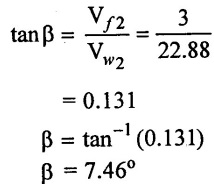
(ii) The angle absolute velocity of water at exit makes with the tangent (β)
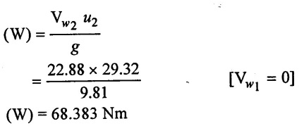
(iii) The workdone per N of water (W)
Solution:
(1) Tangential velocity of impller at inlet
u1 = 13.19 m/s
(2) Tangential velocity of impeller of outlet
u2 = 29.32 m/s
(3) From inlet velocity triangle
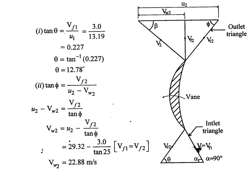 (4) From ioutlet velocity triangle
(5) Workdone per N of water
Result:
(1) Inlet vane angle (θ) = 12.78°
(2) The absolute velocity water at exit make angle β = 7.46°.
Work done per N of water (W) = 68.383 Nm
Example - 2
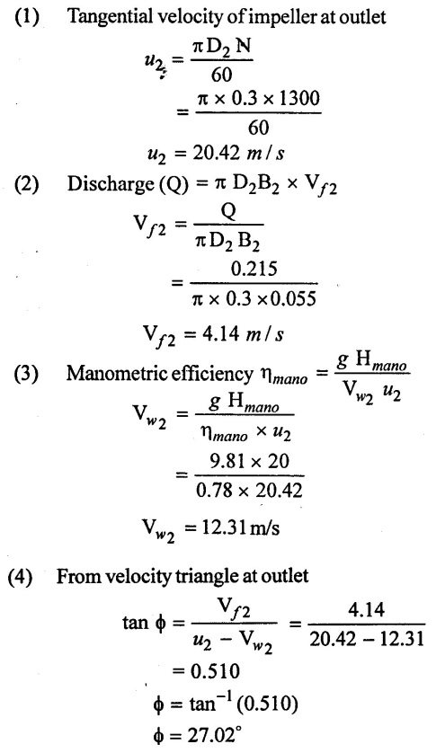
A centrifugal pump is to discharge 0.215m3/s at a speed of 1300 rpm against a head of 20m. The impeller diameter is 300 mm its width at outlet is 55 mm and manometric efficiency is 78%. Determine the vane angle at the outlet periphery of impeller.
Given data:
Discharge (Q) = 0.215m3/s
Sped (N) = 1300 rpm
Manometric head (Hmano) = 20 m
Diameter of impeller at outlet [ D2] = 300 mm =0.3m
Width at outlet (B2) = 55mm = 0.055m
Manometric efficiency (ηmano) = 78% = 0.78
To find:
Vane angle at the outlet periphety of impeller (ϕ)
Solution:
 Result :
Outlet vane angle (ϕ) = 27.02°
Example : 3
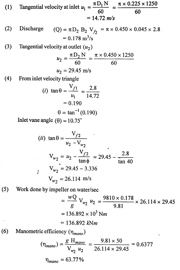
The impeller of a centnrifugal pump having external and internal diameter 450mm and 225 mm respectively. Width at outlet is 45 mm and running at 1250 rpm. Works against a head of 50m. The velocity of flow through the impeller is constant and equal to 2.8 m/s. The vanes at set back at an angle of 40° at outlet. Determine
(i) Inlet vane angle
(ii) Work done by impeller on water per second.
(iii) Manometric efficiency
Given data:
External diameter of impeller (D2) = 450mm = 0.45 m
Internal diameter of impeller (D1) = 225 mm = 0.225 m
Width at outlet (B2) = 45 mm = 0.045 m
Speed (N) = 1250 rpm
Head (Hmano) = 50 m
Velocity of flow Vf1 = Vƒ2 = 2.8 m/s
Vane angle at outlet ϕ = 40°
To find:
(1) Inlet vane angle (θ)
(2) Work done by impeller on water/sec (W)
(3) Manometric efficiency (ηmano)
Solution:
Result :
(1) Inlet vane angle (θ) = 10.75°
(2) Work done by impeller on water/sec (w) = 136.89 kNm
(3) Manometric efficiency (ηmano) = 63.77%
Example : 4
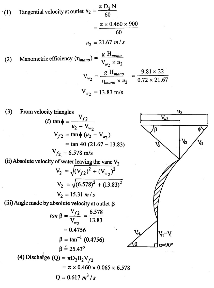
A centrifugal pump running at 900 rpm is working against a total head of 22m. The external diameter of the impeller is 460mm and outlet width 65mm. If the vanes angle at outlet is 40° and manometric efficiency is 72% determine.
(1) Flow velocity at outlet
(2) Absolute velocity of water leaving the vane.
(3) Angle made by the absolute velocity at outlet with the direction of motion
at outlet.
(4) Rate of flow through the pump.
Given data:
Speed (N) = 900 rpm
Head (Hmano) = 22m
External diameter (D2) = 460 mm = 0.460 m
Width at outlet (B) = 65 mm = 0.065 m
Vane angles at outlet (ϕ) = 40°
Manometric efficiency (ηmano) = 72% = 0.72
To find:
(i) Flow velocity at outlet (Vƒ2)
(ii) Absolute velocity of water leaving the vane (V2)
(iii) Angle made by the absoulte velocity at outlet (β)
(iv) Rate of flow through the pump (Q)
Solution:
Result :
(1) Flow velocity at outlet (Vƒ2) = 6.578m/s
(2) Absolute velocity of outlet (V2) = 15.31m/s
(3) Angle made by V2 (β2) = 25.43°
(4) Rate of flow through the pump (Q) = 0.617m3 / s
Example : 5
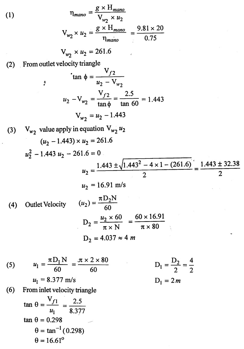
A centrifugal pump impeller runs at 80 rpm and has outlet vane angle of 60°. The velocity of flow is 2.5 m/s throughout and diameter of impeller at exit is twice that at inlet. It the manometric head is 20 m and the manometric efficiency is 75% determine.
(i) The diameter of the impeller at exit
(ii) Inlet vane angle
Given data:
Outlet vane angle ϕ = 60°
Speed (N) = 80 rpm
Velocity of flow Vƒ1 = Vƒ2 =2.5 m/s
Manometric head (Hmano) = 20m
Manometric efficiency (ηmano) = 75% = 0.75
Diameter of outlet D2 = 2 × D1
To find:
(1) The diameter of the impeller at exit (D2)
(2) Inlet vane angle (θ)
Solution:
Result:
(1) Diameter of impeller at exit (D2) = 4m
(2) Inlet vane angle (θ) = 16.61°
Example : 6
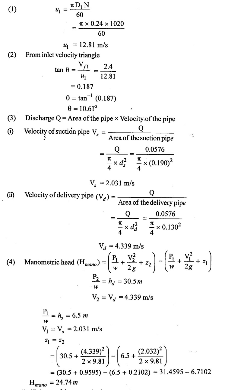
A centrifugal pump impeller having external and internal diameters are 480 mm and 240mm respectively is running at 1020 rpm. The rate of flow through the pump is 0.576 m3/s and velocity of flow is constant and equal to 2.4 m/s. The diameter of the suction and delivery pipes are 190mm and 130mm respectively and suction and delivery heads are 6.5 m and 30.5 m of water respectively. If the power required to drive the pump is 24 kw and outlet vane angle is 45° determine.
(1) Inlet vane angle
(2) The overall efficiency of the pump
(3) The manometric efficiency of the pump
Given data:
External diameter of impeller (D2) = 480 mm = 0.48 m
Internal diameter of impeller (D1) = 240 mm = 0.240 m
Speed (N) = 1020 rpm
Discharge (Q) = 0.576 m3/s
Velocity of flow Vƒ1 = Vƒ2 = 2.4 m/s
Diameter of suction pipe (ds) = 190 mm = 0.190 m
Diameter of delivery (dd) = 130 mm = 0.13 m
Suction head (hs) = 6.5 m
Delivery head (hd) = 30.5 m
Shaft poer (p) = 24 kw = 24 × 103 w
Outlet vane angle ϕ = 45°
To find:
(1) Inlet vane angle (θ)
(2) Over all efficiency (ηo)
(3) Manometric efficiency (ηmano)
Solution:
(5) Overall efficiency of the pump (ηo)
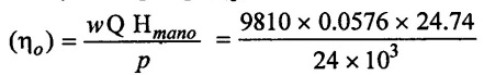
ηo = 0.5824
ηo = 58.24%
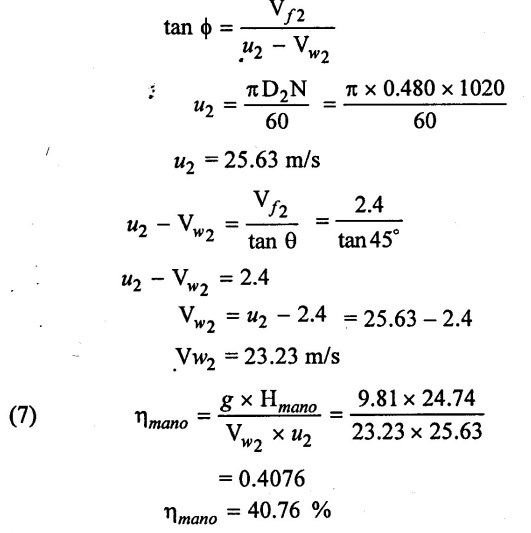
(6) From velocity triangle of outlet
Result:
(1) Inlet vane angle (θ) = 10.61°
(2) Overall efficiency of the pump (ηo) = 58.24%
(3) Manometric efficiency of the pump (ηmano) = 40.76 %
Example: 7
It is required to delivery 0.038m3/s of water to a height of 24 m. Through 160mm diameter pipe and 125 m long by a centrifugal pump. If the overall efficiency of the pump is 72% and coefficient of friction f = 0.01 for the pipe line, find the power required to drive the pump.
Given data:
Discharge (Q) 0.038m3/s
Height (Hstat) = hs + hd = 24m
Diameters of pipe (ds) = 150mm = 0.15m = (dd)
Length of the pipe = Ls + Ld = 125m = (L)
Overall efficiency (ηo) = 72% = 0.72
Co-efficient of friction ƒ = 0.01
To find:
Power required to drive the pump (P).
Solution:
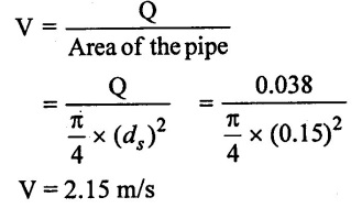
(1) Discharge (Q) Area of the pipe × Velocity of the pipe
Velocity of the pipe V s = Vd [because diameter of the pipe is same ds = dd]
(2) Loss of head due to friction in pipe using Darcy's formula
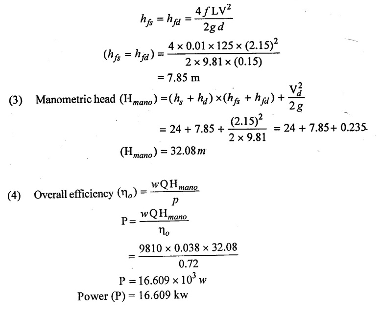
Result :
Power (P) = 16.609 kw
Example : 8
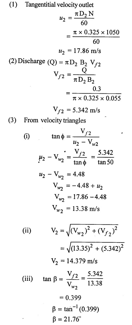
The impeller of a centrifugal pump is of 325 mm diameter and 55 mm width at the periphery, and has blades whose tip angle inclined backwards 50° from the radious. The pump delivers 18 m3/min of water and the impeller totals at 1050 rpm. Assuming that the pump is designed to admit radially calculate
(1) Speed and direction of water as it leaves the impeller
(2) To torque exerted by the impller on water
(3) Shaft power required
(4) Lift of the pump
Take mechanical efficiency = 95% and hydraulic efficiency ηh = 75%
Given data:
External diameter of impeller (D2) = 325 mm = 0.325 m
Width of impeller (B2) = 55 mm = 0.055 m
Outlet vane angle ϕ = 50°
Diacharge (Q) = 18m3/min = 0.3 m3/s
Speed of impeller (N) = 1050 rpm
Mechanical efficiency ηm = 95% = 0.95
Hydraulic efficiency ηh = 75% = 0.75
To find:
(1) Speed and direction of water of it leaves the impeller V2, β
(2) Shaft power required (P)
(3) The torque exerted by the impeller (T)
(4) Lift of the pump
Solution:
(4) Torque (T) = Force exerted by impeller × R2
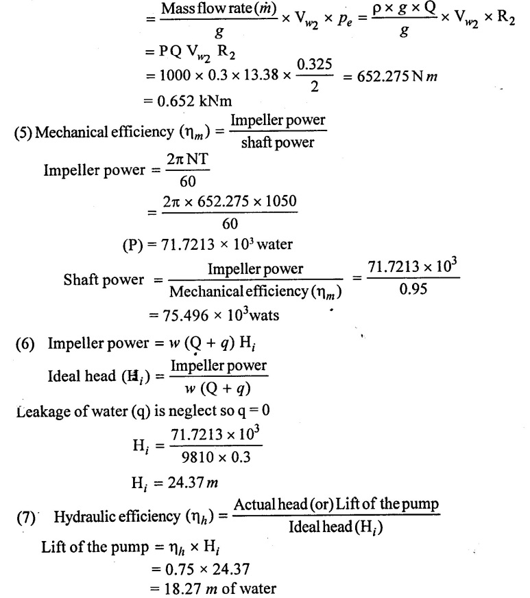
Result:
(1) Speed (V2) = 14.406 m/s
(2) Direction of water of it leaves (β) = 21.76°
(3) Toraue exerted by impeller (T) = 652.275 Nm
(4) Shaft power (P) = 75.496 × 10³ w
(5) Lift of the pump = 18.27 m of water
Example: 9
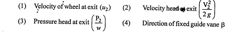
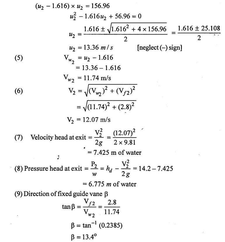
A centrifugal pump has suction lift of 1.8m and the delivery tank is 14.2 m above the pump. The velocity of water in the delivery pipe is 1.6 m/s the radial velocity of flow through the wheel is 2.8 m/s and the tangent to the vane at the exit from the wheel makes on angle of 120o with the direction of motion. Assuming that the water enters radially and neglecting friction and other losses determine: (i) Velocity of wheel of the exit
(ii) Velocity and pressure head at exit from the wheel
(iii) Direction of the fixed guide vane
Given data:
Suction lift (or) head (hs) = 1.8m
Delivery head (hd) = 14.2m
Velocity of water in delivery pipe (Vd) = 1.6 m/s
Velocity of flow Vf1 = Vƒ2 = 2.8 m/s
Outlet vane angle ϕ = 180° – 120 = 60°
To find:
Solution:
(1) Total head (H) = hs + hd
= 1.8 + 14.2
H = 16 m of water
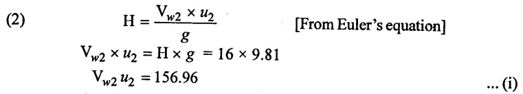
(3) From outlet velocity triangle
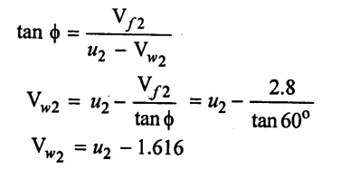
(4) Vw2 value apply in equation (i)
Result:
(1) Velocity of wheel at exit (u2) = 13.36 m/s
(2) Velocity head of exit  = 7.425 m of water
(3) Pressure head at exit  = 6.775 m of water
(4) Direction of fixed vane (β) = 13.4°
Example: 10
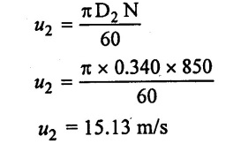
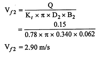
A centrifugal pump impeller has of outlet at a diameter of 340 mm and width 62 mm. The vanes are curved backwards at 40° to the tangent at outlet peripety and thickness of vanes occupipes 22 percent of the peripheral area and the velocity of flow is constant from inlet to outlet. The impeller rotates at 850 rpm. If the rate of flow through the pump is 0.15 m3/s determine:
(i) The pressure rise in the impeller
(ii) The percentage of total work converted to kinetic energy.
Given data:
Diameter of the impeller at outlet (D2) = 340 mm = 0.340 m
Width of impeller of outlet (B2) = 62 mm = 0.062 m
Outlet vane angle ϕ = 40°
Area occupied by thickness of vanes = 22% of the peripheral area.
Thickness co-efficient Kt = 1−0.22 = 0.78
Speed (N) = 850 rpm
Discharge (Q) = 0.15 m3/s
To find:
(1) Pressure rise in the impeller
(2) % of work converted to kinetic energy
Solution:
(1) Tangential velocity of impeller at outlet
(2) Rate of flow Q = Kt × π × D2 B2 Vƒ2
(3) From outlet velocity triangle
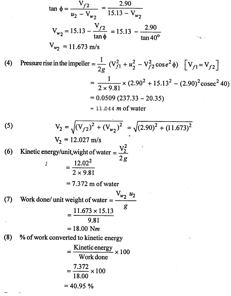
Result:
(1) Pressure rise in the impeller = 11.044 m of water
(2) % of work converted to kinetic energy = 40.95%
Example : 11
A centrifugal pump, in which water enters radially, delivers water to a height of 165 mm. The impeller has diameter of 360 mm and width 180 mm of inlet and the corresponding at the outlet are 720 mm and 90mm respectively, its rotational speed is 1200 rpm. The blade are curved back ward at 30° to the tangent at exit and the discharge is 0.389 m3/s. Determine.
(i) Theoretical head developed
(ii) Manometric efficiency
(iii) Pressure rise across the impeller assuming Losses equal to 12% of velocity
head at exit.
(iv) Pressure rise and the loss of head in the volute casing
(v) The vane angle at inlet
(vi) The power required to drive the pump assuming an overall efficiency 75%. What would be corresponding mechanical efficiency?
Given data:
Manometric head (Hmano) = 165 m
Diameter of impeller at inlet (D1) = 360mm =0.36 m
Width at inlet B1 = 180 mm = 0.18 m
Diameter of impeller at outlet D2 = 720 mm =0.72 m
Width at outlet B2 = 90 mm = 0.09 m
Speed (N) = 1200 rpm
Outlet vane angle ϕ = 30°
Discharge (Q) = 0.389 m3/s
Overall efficiency (ηo) = 75%
To find:
(1) Theroretical head He (or) Euler head
(2) Manometric efficiency (ηmano)
(3) Pressure rise across the impeller
(4) Pressure rise and loss of head in casing
(5) Inlet vane angle (θ)
(6) Power required to drive the pump
(7) Mechanical efficiency (ηm).
Solution:
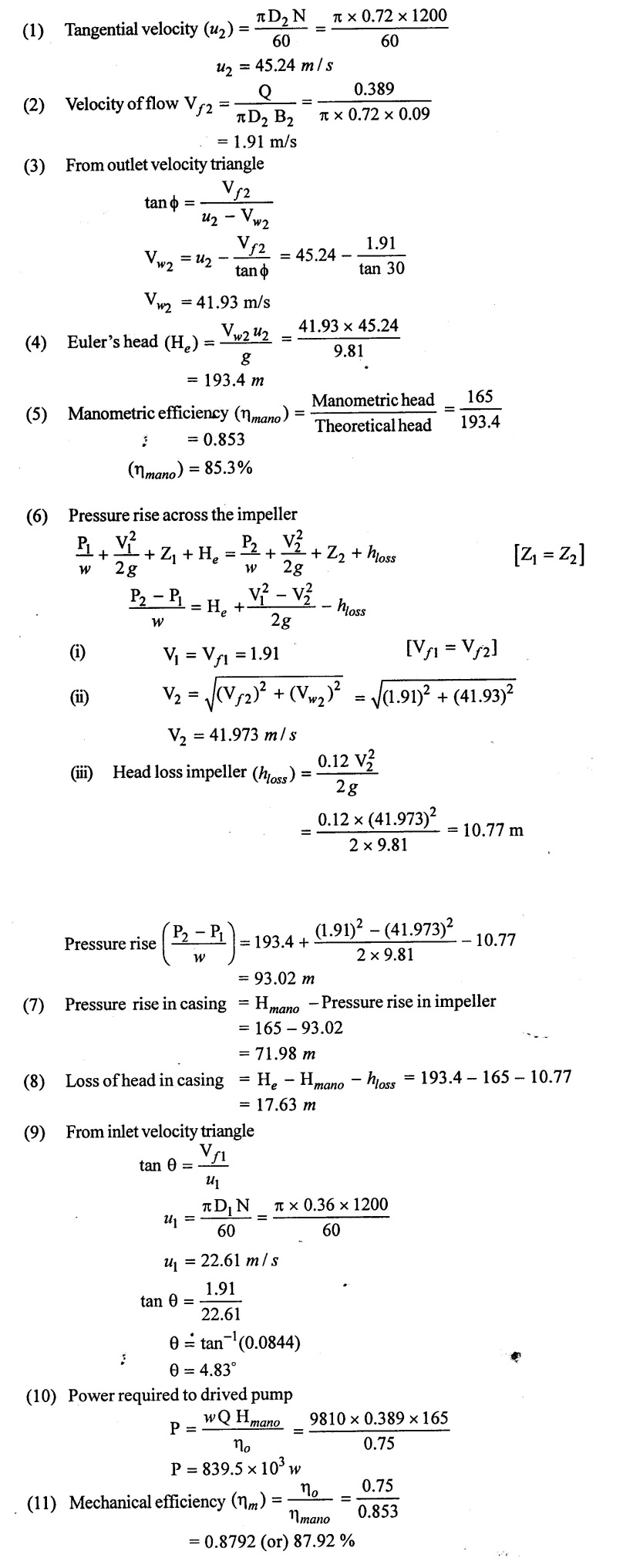
Result :
(1) Theoretical head (He) = 193.4m
(2) Manometric efficiency (ηmano) = 85.3%
(3) Pressure rile across the impeller = 93.02 m
(4) Pressure rise in casing = 71.98 m
(5) Loss of head in casing = 17.63 m
(6) Inlet vane angle θ = 4.8
(7) Power requird to drive the pump (P) = 839.5 × 10³ w
(8) Mechanical efficiency (ηm) = 87.92%
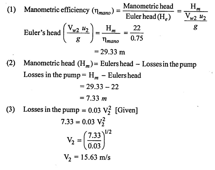
Example : 12
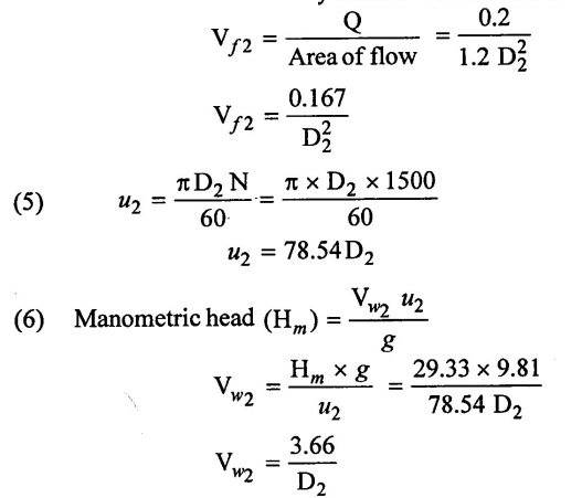
A centrifugal pump is required to discharge 0.2m3 of water per second against a head of 22 m when the impeller rotates at a speed of 1500 rpm. The manometric efficiency is 75 % the loss of head in pump in metre due to fluid resistance is 0.03 V22. Where V2 m/s is the velocity of water leaving the impeller. The area of the impeller outlet surface is 1.2 D22 m2. Where D is impeller diameter in m, determine
(i) The impeller diameter
(ii) Outlet vane angle
Assume that the water enters the impeller without whirl
Given data:
Discharge (Q) = 0.2 m3/s
Manometric head (Hmano) = 22m
Speed of the impeller (N) = 1500 rpm
Manometric efficiency (ηmano) =75%
Loss of head due to fluid resistance = 0.03 V22
Area of impeller outlet surface = 1.2D22
To find:
(1) Impeller diameter (D2)
(2) Outlet vane angle (ϕ)
Solution:
(4) Discharge (Q) = Velocity of flow × Area of flow
(7) From velocity triangle
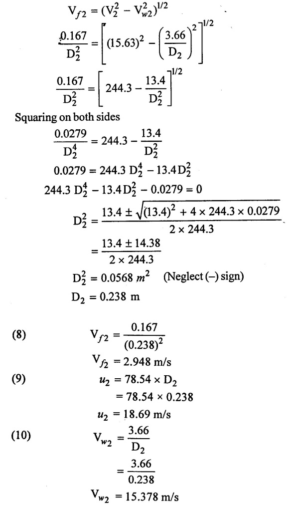
(11) From out velocity triangle
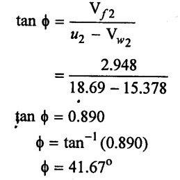
Result:
(1) Impeller diameter (D2) = 0.238 m
(2) Outlet vane angle (ϕ) = 41.67°
Example: 13
A three stage centrifugal pump has impeller 350mm in diameter and 25 mm wide at outlet. The vane angle at outlet is 40o and the area occupied by the thickness of the vanes may be assumed 10% of the total area. If the pump delivery 3.6m3 of water per minutes when running at 900 rpm.
Determine:
(i) Power of the pump
(ii) Manometric head
(iii) Specific speed.
Assume mechanical efficiency as 88 % and manometric efficiency as 77%
Given data:
Number of stage (n) = 3
Diameter of impeller at outlet D2 = 350 mm = 0.35 m
Width of impeller at oulet β2 = 25 mm = 0.025 m
Outlet vane angle ϕ = 40°
Area occupied by thickness of vanes = 10% of the total area
Discharge (Q) = 3.6m3/min = 0.06 m3/s
Speed (N) = 900 rpm
Mechanical efficiency (ηm) = 88% = 0.88
Manometric efficiency (ηmano) = 77% = 0.77
To find:
(1) Manometric head (Hmano)
(2) Power of the pump (P)
(3) Specific speed
Solution:
 Result:
(1) Manometric head Hm = 52.76m
(2) Power of the pump = 45.83 kw
(3) Specific speed of the pump (Ns) = 25.66 rpm
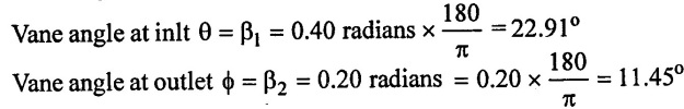
Example : 14
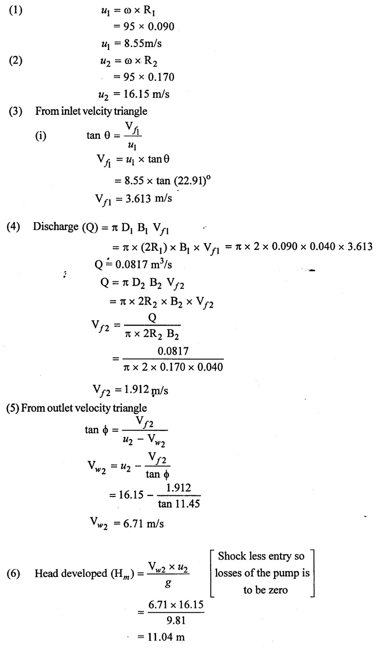
A centrifugal pump has the following dimensions inlet radius = 90mm outlet radius = 170 mm, width of impeller at the inlet = 40 mm β1 = 0.40radians β2 = 0.20 radians width of impeller at outlet = 40 mm. Assuming shockless entry determine the discharge and the head developed by the pump when the impeller rotates at 95 rad/sec.
Given data:
Inlet radius R1 = 90mm = 0.090m
Outlet radius R2 = 170mm = 0.17 m
Width of inlet B1 = 40mm = 0.040 m
Width at outlet B2 = 40mm = 0.040 m
Angle β1 = 0.40 radians β2 = 0.20 radians
Angular velocity ω = 95 rad/s
To find:
(1) Discharge (Q)
(2) Head developed by the pump (Hm)
Solution:
Result:
(1) Discharge (Q) = 0.0817 m3/s
(2) Head developed (Hm) = 11.04m
Example : 15
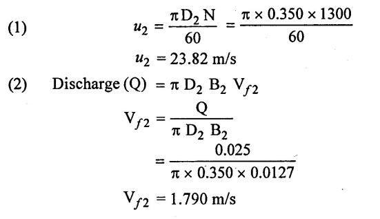
A centrifugal pump delivery 1.5m3 of water per minute at 1300 rpm. The impeller diameter is 350 mm and width at outlet is 12.7 mm. The pressure difference between inlet and outlet of pump casing is 282 kN/m2. Calculate the impeller exit blade angle and manometric efficiency 65%.
Given data:
Discharge (Q) = 15m3/min = 0.025 m3/s
Speed (N) = 1300 rpm
External diameter of impeller (D2) = 350 mm = 0.350 m
Width at outlet (β2) = 12.7 mm = 0.0127m.
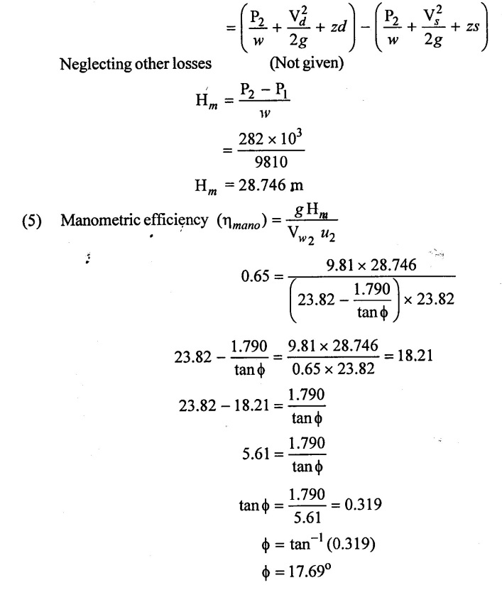
Pressure difference (p2 − p1) = 282 kN/m2 = 282 × 103 N/m2
Manometric efficiency (ηmano) = 65% = 0.65
To find:
Impeller exit blade angle (ϕ)
Solution:
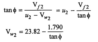
(3) From outlet velocity triangle
(4) Manometric head (Hm) = Total head of outlet - Total head at inlet
 Result:
Outlet vane angle ϕ = 17.69°
Example: 16
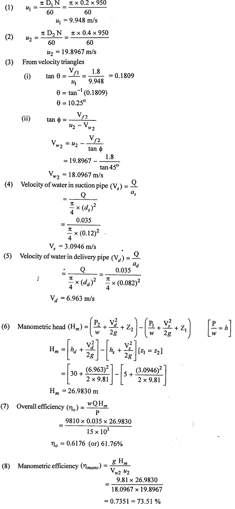
A centrifugal pump impeller whose external and internal diameter are 400 mm and 200 mm respectively is running at 950 rpm. The rate of flow through the pump is 0.035 m3/s. The suction and delivery heads are 5 m and 30m respectively. The diameter of the suction and delivery pipes are 120mm and 80mm respectively. If the outlet vane angle is 45° the flow velocity is constant and equal to 1.8 m/s and power required to drive the pump is 15 kw determine (1) inlet angle (2) The overall efficiency (3) The manometric efficiency.
Given data:
External diameter of impeller (D2) = 400mm = 0.4 m
Internal diameter of impeller (D1) = 200mm = 0.2 m
Speed (N) 950 rpm
Discharge (Q) = 0.035 m3/s
Suction head (hs) = 5m
Delivery head (hd) = 30m
Diameter of suction pipe (ds) = 120mm = 0.120m
Diameter of delivery pipe (dd) = 80mm = 0.08m
Outlet vane angle (ϕ) = 45°
Flow velocity Vƒ1 = Vƒ2 = 1.8 m/s
Power (P) 15 kw = 15 × 103w
To find:
(1) Inlet vane angle (θ)
(2) Overall efficiency (ηo)
(3) Manometric efficiency (ηmano)
Solution:
Result :
(1) Inlet angle (θ) = 10.25°
(2) Overall efficiency (ηo) = 61.76%
(3) Manometric efficiency (ηmano) = 73.5%
Example: 17
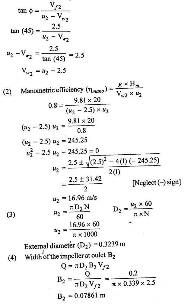
A centrifugal pump is running at 1000 rpm and working against a head of 20m. The rate of flow through the pump is 0.2 m3/s. The outlet vane angle of impeller is 45o and velocity of flow at outlet is 2.5 m/s. If the manometric efficiency of the pump is 80%. Calculate the diameter and width of impeller at outlet.
Given data:
Speed (N) = 1000 rpm
Manometric head (Hm) = 20 m
Discharge (Q) = 0.2 m3/s
Outlet vane angle ϕ = 45°
Velocity of flow at outlet (Vf2) = 2.5 m/s
Manometric efficiency (ηmano) = 0.8
To find:
(1) External diameter at outlet (D2)
(2) Width of impeller at outlet (B2)
Solution:
(1) From outlet velocvity tiangle
Result :
(1) Outlet diameter (D2) = 0.32039 m
(2) Outlet width (B2) = 0.07861 m
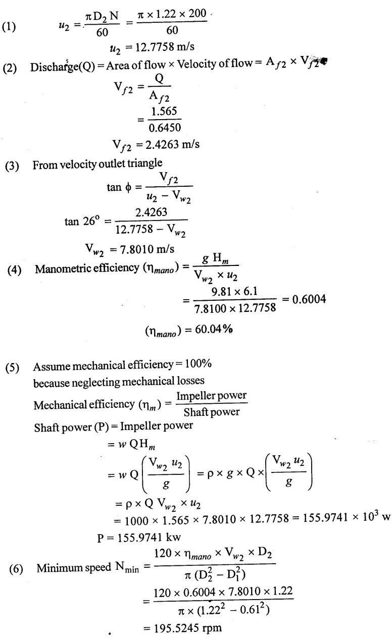
Example: 18
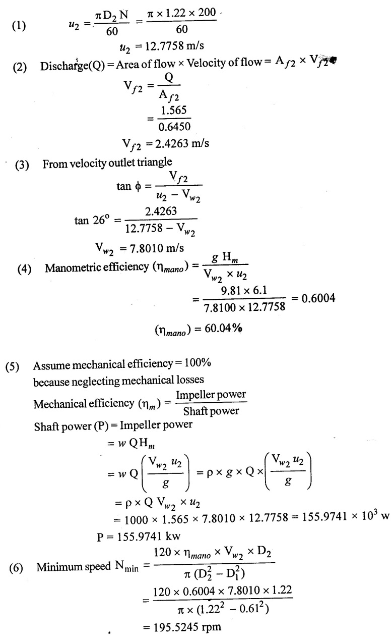
A centrifugal pump delivers 1565 LPS against a manometric head of 6.1 m when the impeller rotates at 200 rpm. The impeller diameter is 1.22 m and the area of outlet periphery is 6450 cm2. If the vanes are set back at an angle of 26° at the outlet determine.
(1) Manometric efficiency
(2) Power required to drive the pump
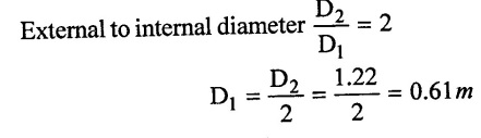
(3) Minimum starting speed if ratio of external to internal diameter is 2.
Given data:
Discharge (Q) = 1565 lps = 1.565 m3/s
Manometric head (Hm) = 6.1m
Speed(N) = 200 rpm
External diameter of impeller (D2) = 1.22m
Outlet periphery area (Aƒ2) = 6450 cm2 = 0.645 m2
Outlet vane angle (ϕ) = 26°
To find:
(1) Manometric efficiency (ηmano)
(2) Power rrequired
(3) Minimum starting speed.
Solution:
Result :
(1) Manometric efficiency (ηmano) = 60.04%
(2) Power required (P) = 155.9741 kw
(3) Minimum starting speed (Nmin) = 195.524 rpm
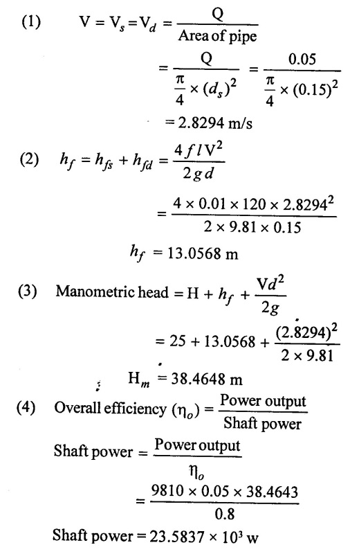
Example: 19
It is required to delivers 0.05m3/s of water to a height of 25 m. Through a 150 mm diameter pipe and 120m long by a centrifugal pump. If the overall efficiency of the pump is 80% and co-efficient of friction f = 0.07 for the pipe line. Find the power required to drive the pump.
Given data:
Discharge (Q) = 0.05 m3/s
Total height (H) = hs + hd = 25m
Diameter of pipe ds = dd = 150 mm = 0.15 m
Length of pipe L = Ls + Ld = 120m
Overall efficiency (ηo) = 80% = 0.80
Co-efficient of friction (f) = 0.01
To find:
Power required to drive the pump.
Solution:
Result :
Power required (P) = 23.5837 × 10³ w
Example : 20
A centrifugal pump has an impeller 500mm in diameter at outlet and running at 400 rpm. The discharge at the inlet is enters radial. The velocity of the flow at outlet is 1 m/s the vanes are curved back wards at outlet is 30° to the wheel tangent. If the discharge of the pump is 0.14m3/s. Calculate the impeller power and the torque on the shaft.
Given data:
External diameter of impeller (D2) = 500 mm = 0.5 m
Speed (N) = 400 rpm
Flow velocity at outlet Vƒ2 = 1 m/s
Outlet vane angle ϕ = 30°
Discharge Q = 0.14 m3/s
To find :
(1) Torque
(2) Impeller power
Solution:
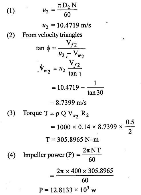
Result:
(1) Torque (T) = 305.8965 Nm
(2) Power (P) = 12.8133 × 10³ w
No comments:
Post a Comment