Lester A pelton of California (USA) designed a impulse turbine which is known as pelton turbine (or) wheel. The pelton turbine is the most commonly used type of impulse turbine. This turbine is also called free jet or constant pressure (or) tangential flow impulse turbine
1. Characteristics of pelton wheel turbine
✓ It is a impulse turbine.
✓ Only kinetic energy of water is available at inlet of turbine.
✓ It is working of high head and low discharge.
✓ Work is done only due to change in kinetic energy of water.
✓ Working pressure is equal and constant at atmospheric pressure.
✓ It is a Tangential flow and low specific speed turbine.

From figure 5.4 the main components of a pelton wheel turbine are,
(a) penstock,
(b) nozzle
(c) Spear,
(d) Runner and buckets
(e) Deflector
(f) casing
(g) Brake nozzle.
(a) Penstock
It is a rigid pipe which is used to carries the water from reservoir through the dam gate valve to the turbine under the pressure. The penstock is provided with control valves for the regulation of water flow to the turbine.
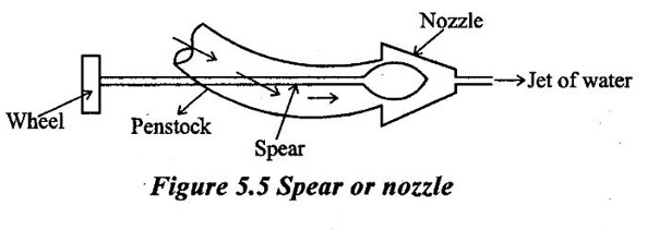
(b) Nozzle
It is used to convert the net available pressure energy of the water into kinetic energy by the nozzle in the form of jet. The jet of water coming from the nozzle strikes the buckets with a high velocity and leaves the buckets with comparatively low velocity and produces impact on the buckets. Due to this impact, turning moment act on the runner which rotates the runner at a high speed.
(c) Spear
It is used to regulate the flow rate of water into the turbine. Due to linear movement of the spear, space between nozzle and spear increases (or) decreases in such a way, so flow rate of water also increase (or) decrease accordingly as shown in figure 5.5.
(d) Runner and buckets
Runner of a pelton turbine is a circular disc which is mounted on a horizontal shaft. The buckets are fixed to the periphery of the runner uniformly at equal distance. The shape of the bucket is like a double hemispherical cup. Each bucket is divided vertically into two part by a splitter. The splitter splits the jet of water into two equal parts without any shock. The two parts of the same jet move side ways in opposite direction.
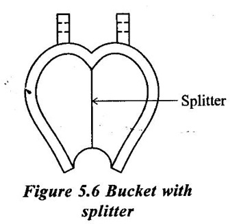
The jet is deflected by the buckets through an angle of 160° to 170°. Average value is taken as 165°. The buckets are generally fastened by two (or) more both to the runner as shown in figure 5.6.
(e) Deflector
A deflector is provided which is hinged to the casing to deflect the set of water away from striking the buckets in case the load on turbine suddenly reduces.
It prevents the runner of turbine attaining unsafe speeds are called runaway speed.
(f) Casing
The casing of the pelton wheel turbine do not perform any hydraulic function. It prevent the splashing of water and discharge the water into tail race. It can also be used as a safe guard against accidents.
(g) Brake nozzle
It is used to stop the rotation of the runner in a short period of time. When stopping the runner, firstly water supply to the turbine is stopped by operating the spear and then braking jet of water issuing from the brake nozzle will strike on the back of the buckets.
This braking jet exerts torque on the runner in opposite direction of motion of the runner. This opposite torque is known as brake torque and responsible to stops the runner in a short period of time.
Working:
The penstock carrying water from the reservoir at high head to the turbine, it is connected to a branched pipe fitted with the nozzle at the end. The whole of the pressure energy of the water is converted into the kinetic energy with the help of nozzle before supply to the turbine runner. The water comes out of the nozzle in the form of a jet with very high velocity. This high velocity of jet is strike on a series of buckets mounted on the periphery of a wheel keyed to the turbine shaft. The impulsive force of the jet exerted on the series of buckets setup the wheel in rotation in the directino in which jet is impinging. The water as it flow over the buckets, the velocity of flow will be decrease and atmospheric pressure remain constant. This turbine in also called constant pressure turbine (or) velocity turbine (or) free jet turbine. Pelton wheel turbine is best suited for high head and low discharge.
2. Losses of pelton turbine
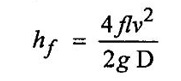
(a) Head loss in the penstock
Head loss due to friction between water and penstock is called head loss in the penstock. It is calculated by Darcy's formula.
(b) Head loss in the nozzle:
Pressure energy at the inlet of the nozzle does not completely converted into kinetic energy at the outlet, some of the energy lost due to friction inside the nozzle. This energy lost due to friction is called head loss in the nozzle.
(c) Hydraulic fosses:
This losses are due to bucket friction, eddy formation and kinetic energy of leaving water.
(d) Leakage losses:
The whole jet of water does not strike on the buckets. Therefore, some of energy of water go for waste. This loss is called as leakage loss.
(e) Mechanical losses:
The power available at shaft is always less than power produced by the runner because some power is consumed in overcoming friction in bearing and some in overcoming friction in bearing and some in overcoming the windage losses. So the losses due to bearing friction and windage are called mechanical losses.
(f) Generator losses:
In generator, complete input shaft power (or) mechanical power is not converted into electrical power, some input shaft power can be lost in generator, is called generator loss.
3. Velocity triangle of pelton turbine and workdone

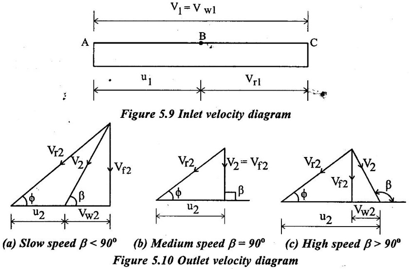
Consider a water jet striking at the splitter of a bucket as shown in figure 5.8. The velocity triangles of the water jet are drawn at the inlet and outlet of the bucket as shown in figure 5.7. The symbols used for determining workdone by jet from velocity triangles are
N - Speed of the wheel (or) turbine.
D - Diameter of the pelton wheel.
D - diameter of jet.
u - peripheral velocity of runner.
V1 - absolute velocity of jet at inlet.
V2 - absolute velocity of jet at outlet.
Vrl = Relative velocity of the jet to the bucket at inlet.
Vr2 = Relative velocity of the jet to the bucket at outlet.
Vwl = Component of velocity of jet V1 in the direction of motion of bucket at inlet (or) Whirl velocity at inlet.
Vw2 = Component of velocity V2 in the direction of motion of bucket at inlet (or) Whirl velocity at outlet.
Vƒ1 = Component of velocity of jet V1 in the direction perpendicular to the motion of buckets (or) Flow velocity at inlet.
Vf2 = Component of velocity V2 in the direction perpendicular to the motion of buckets (or) Flow velocity at outlet.
α = Angle between the direction of jet and direction of motion of the bucket at inlet (or) Guide blade angle at inlet.
β = Angle made by absolute velocity V2 with the direction of motion of bucket at outlet (or) Guide blade angle at outlet.
θ = Angle made by the relative velocity Vr1 with the direction of motion of bucket at the inlet (or) vane angle at inlet.
ϕ = Angle made by the relative velocity Vr2 with the direction of motion at outlet (or) Vane angle at the outlet.
From Inlet velocity triangle
The velocity triangle at inlet will be a straight line because the jet of water is entering the bucket in same direction in which bucket is moving.
So Vf1 = 0
Vω1 = V1
Vr1 = v1 – u1 = v1 – u (u = u1 = u2)
Inlet angles α & θ = 0
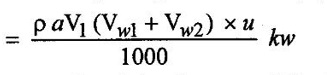
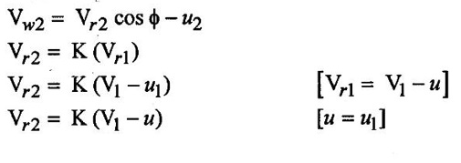
(ii) From outlet velocity triangle
As the water passes over the curved surface of bucket Vr2 becomes less than Vr1 due to frictional loss therefore,
Vr2 = k Vr1 [K= co-efficient of friction k < 1]
For general purpose these frictional losses are neglected and k is taken as unity.
Therefore
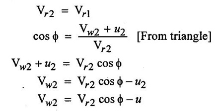
Vw2 depends upon angle β.
(i) For slow speed runner β < 90° Vw2 is negative.
For medium speed runner β = 90° Vw2 = 0.
(iii) For high speed runner β > 90° Vw2 in positive
From the above three cases, commonly used slow speed runner, so take the value of Vw2 is negative sign.
(iii) Force exerted by the jet of water in the direction of motion
Fx = Mass flow rate x change in whril velocity
= ρaV1 × [Vwl (+ Vw2)]
⸫ [β > 90 For fast runner] so Vw2 is positive sign (+ve)
(i) Fx = ρaV1 (Vwl - (+Vw2)) ⸫ Vw2 is positive sign (+ve)
Fx = ρaV1 (Vwl - Vw2) [β > 90° - Fast runner]
(ii) Fx = ρaV1 (Vwl - (-Vw2)) ⸫ Vw2 is negative sign (-ve)
Fx = ρaV1 (Vwl + Vw2) [β < 90° - Slow runner]
(iii) Fx = ρaV1 (Vwl) ⸫ Vw2 = 0 [β = 90° - Medium speed-runner]
Commonly used Vw2 is negative, Assume runner is slow speed and β < 90°, so,
Fx = ρaV1 (Vwl + Vw2)
a = area of the jet = π/4 × d2
ρ = Density of the liquid.
(iv) Workdone by the jet on the runner/sec = Force × Velocity
ρaV1 (Vwl + Vw2) × u in N m/s
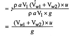
(v) Power produced by the pelton wheel (P) = (Workdone/sec) / 1000
(vi) Workdone per unit weight of water striking/sec = (Workdone/sec) / Unit weight of water striking
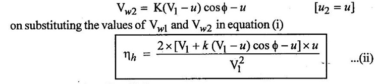
(vii) Hydrautic efficiency (hh) = (Workdone/sec) / kinetic energy supplied by the jet of inlet
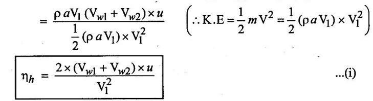
above equation (i) is also called blading efficiency (or) bucket efficiency (ηb).
From velocity triangles Vw1 = V1
So
(viii) Maximum hydraulic efficiency
Absolute velocity of jet (V1) and hydraulic efficiency depends upon the peripheral velocity (u) of the runner. Hence, for obtaining maximum efficiency condition is
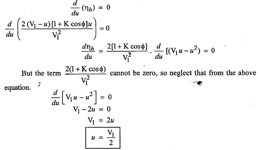
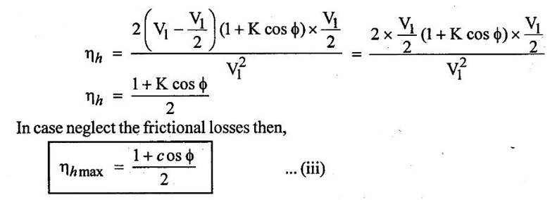
The above shows that a pelton wheel will have maximum efficiency when velocity of wheel (u) is half of the velocity of the jet (V1) at inlet of the turbine. Hence the value of u is apply in equation (ii).
4. Efficiencies of Pelton wheel turbine
1. Hydraulic Efficiency (ηh) (or) Bucket efficiency (ηb):
It is defined as the the ratio of power delivered by the runner to the power available with the water at inlet of the turbine.

Net head = H
Hydraulic losses within the turbine ΔH = H - Hr
Hr = H - ΔH
Hydraulic efficiency of pelton wheel turbine = 0.91 to 0.93.
2. Mechanical efficiency (ηm)
Mechanical efficiency is defined as the ratio of the power available at the turbine shaft to the power developed by the turbine runner. It takes into account the loss of power due to frictional effect of running parts.
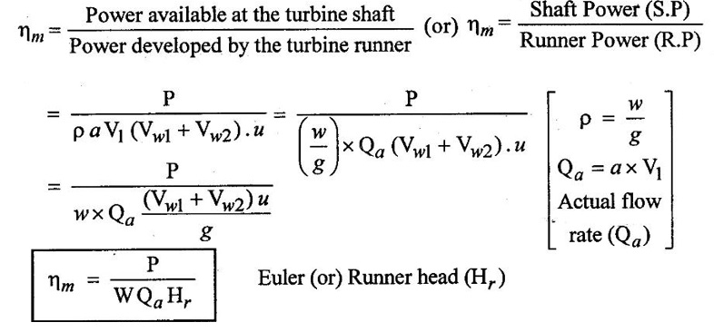
Values of Mechanical efficiency for a pelton wheel turbine lies between 0.96 to 0.98.
3. Volumetric efficiency (ηv)
The volumetric efficiency is defined as the ratio of the volume of water actually striking the runner to the volume of water supplied by the jet to the turbine (or) Total discharge.
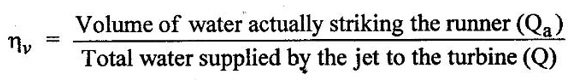
ηv Values lies between 0.97 to 0.99.
4. Overall efficieney (η0)
It is defined as the ratio of power available at the turbine shaft to the power available with water at the inlet of the turbine.
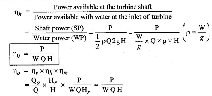
Overall efficiency (η0) = 0.85 to 0.90
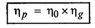
5. Hydro - electric plant efficiency (ηp)
It is the product of overall efficiency of the turbine (η0) and efficiency of the generator (ηg)
5. Design aspects of pelton wheel
The following parameters are considered while designing a pelton turbine,
(1) Jet Velocity (V1)
The jet velocity at the inlet of the turbine depends upon the net head (H) and it is given as
V1 = Cv √2gH
Cv = Co-efficient of velocity values lies between 0.968 to 0.99.
H = Net head.
(2) Velocity of wheel (or) peripheral velocity of turbine (u)
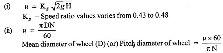
(3) Jet ratio (m)
Jet ratio is defined as the ratio of wheel diameter (D) to the Jet diameter (d).
m = D/d
Values varies from 11 to 16 for maximum efficiency and 12 for most cases.
(4) Angle of deflection of the jet (ϕ)
The angle of deflection of the jet through the buckets is taken as 165°, if no angle of deflection is given.
(5) Number of Jets:
Number of Jets can be determined by dividing the total rate of flow through the turbine by the rate of flow of water through a single jet.
Number of Jets (n) = Q/q
Where
Q = Total discharge
Discharge in one jet = π/4 × d2 × V1
(6) Bucket dimensions
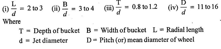
(7) Number of Buckets (z) on a runner.
Z = 15 + D/2d
= 15 + 0.5 D/d
Z = 15 + 0.5 m
The volumetric efficiency is depends on number of buckets.
No comments:
Post a Comment