The study of the flow of fluids in pipes, the concepts of hydraulic gradient line and total energy line is very much important.
HYDRAULIC GRADIENT LINE AND ENERGY GRADIENT LINE
1. Introduction
The study of the flow of fluids in pipes, the concepts of hydraulic gradient line and total energy line is very much important. Its graphically represents the total loss of energy and loss of pressure head or piezometric head at different points of the pipe in direction of flow with respect to Datum line of from the centre line of the pipe.
2. Total Energy Line (TEL) (or) Energy Gradient Line (EGL)
Total energy line is the sum of pressure head (p/w), velocity head (V2/2g) and datum head (Z) with respect to datum line. Total energy line has above hydraulic gradient line by velocity head (V2/2g)
Total energy or head /unit weight (or) TEL = 
When fluid flow through pipes we can measure the total head at various points along the axis of the pipe. And if these points are joined, we get Total energy line (TEL) or Energy Gradient Line (EGL). When the fluid flows though pipe there is a loss of head (energy) in the pipe and energy decreases in the direction of flow.
3. Hydraulic Gradient Line (H.G.L)
It is the sum of pressure head (p/w) and datum head (Z) with respect to datum line. Hydraulic gradient line always below the total energy line by (V2/2g)
Hydraulic gradient line (or) piezometric head H.G.L = p/w + Z
When the fluid flows through pipe, we can measure (p/w + Z) piezometric head at various points along the axis of the pipe. And these points are joined to get Hydraulic gradient line (HGL)
4. Important Aspects of TEL and HGL
1. TEL always drops in the direction of flow due to loss of head occurring in the direction of flow.
2. H.GL may rise (or) fall as it depends upon pressure changes. H.GL rises during flow through a sudden expansion and falls during flow through a sudden contraction.
3. HGL lines always below the TEL lines and distance between TEL and HGL is equal to the velocity head. (V2/2g)
4. If cross section of pipe is uniform (no taper) then the slopes of HGL and TEL are same.
5. There is no relation between TEL and slope of the center line of pipe
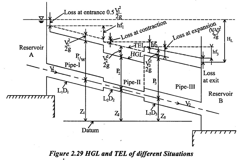
Consider a pipe line carrying liquid from a reservoir A to B as shown in fig.2.29 The two reservoir connected through a pipes 1, 2 and 3. The pipe 1 diameter is higher than pipe 2 diameter and pipe 2 diameter is less than pipe 3 diameter
Measure the pressure head of the all points of the pipe line and drawn the line through that points and get the hydraulic gradient line.
Note that pressure head in pipe line rises during flow through a sudden expansion and falls during flow through a sudden contraction. Also note that EGL will always decrease in direction of flow because some losses will occur here such as entry exit and sudden enlargement sudden contraction and friction losses should be shown on EGL lines is fig 2.29.
5. Solved Examples based on H.G.L & T.E.L lines
Example - 65
A horizontal pipe of 300mm diameter and 80m long is connected to a water tank of one and discharges freely to atmosphere of the other end. If height of the water in the tank is 5m above the center of the pipe. Calculate the rate of flow of water. Consider all loses and take ƒ = 0. 009. Also draw the hydraulic grade line (H.GL) and Total energy line(T.E.L)
Given data:
Diameter of the pipe (d) = 300mm = 0.3m
Length of pipe (L) = 80m
Height of water or total head H = 5m
co-efficient of friction f = 0.009
To find:
(i) Rate of flow of water (Q)
(ii) Draw the HGL and TEL
Solution:
(1) Apply Bernoulli's equation
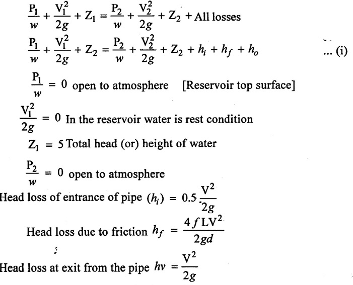
Z2 = 0 Axis of pipe is in the datum line
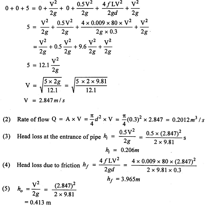
Apply all the values in equation (i)
(6) Total Energy at various points
Consider point A of free surface of water in the tank, point A at inlet of pipe and point C of outlet of pipe as shown in fig.
Consider center line of pipe as datum line
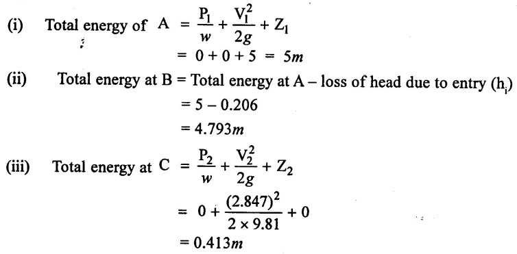
(7) Hydraulic gradient energy at various point
[5 (0.206 + 3.965 +0.413) - 0.413] = 0.413 - 0.413
= 0
= (5 - 0.206) - 0.413
= 4.381 m
(8) Step to draw the EGL (or) TEL
(i) Mark D on free water surface of the tank at distance of 5 m from the datum line point B.
(ii) Mark E in the line AB and below the point D at distance of equal to h1 = 0.413.
(iii) From E, draw a horizontal line which is intersect the vertical line from point C and mark it as point S.
(iv) Mark point F on line CS at distance equal to hf = 3.965 m from point S.
(v) Now joint points D.E.F and get the total energy line and line FC = h0 = 0.413 m.
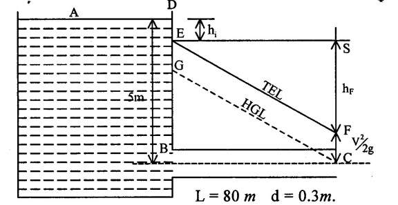
(9) Steps to draw H.G.L Line
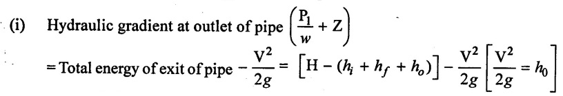
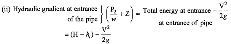
(i) Piezometric head at the entrance of pipe is 4.381m, so the point G is placed at a distance of 4.381m from the point B of datum line
(ii) Piezometric head at exit of the pipe is on there is a point 'C' is placed on the datum line (Exit piezometric head is zero)
(iii) Points G and C are jointed by straight line and the line GC represents the HGL.
Result
Rate of flow (Q) = 0.2012 m3/s
Example - 66
Two reservois are connected by a horizontal pipe of diameter 250mm and Length 200m. If the flow of water through the pipe is 0.8 m3/s calculate the distance in elevantion between the water surfaces of reservoir. If height of the water in main reservoir is 550m, consider all loses. Take f=0.008 also draw HGL and TEL
Given data
Diameter of pipe d1 = 250mm = 0.25m
Length of the pipe L = 200m
Discharge Q = 0.8 m3/s
Height of water in main reservoir (HL) = 550m
Coefficient of friction f = 0.008
To find
i) Difference in head two reservoirs
ii) Draw HGL and TEL
Solution
(1) Rate of flow Q = A × V
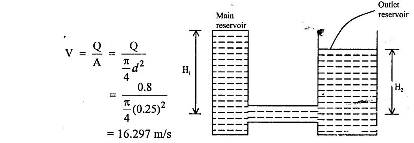
(2) H1 - Height of water of main reservoirs
H2 - Height of water in outlet reservoir
Difference in elevation between reservois H = H1 - H2
Apply Bernoullis equation for free surface of water in the two tanks
H1 = H2 + All loses ….(i)
(3) Following losses occur in the pipe line as shown in fig (i)
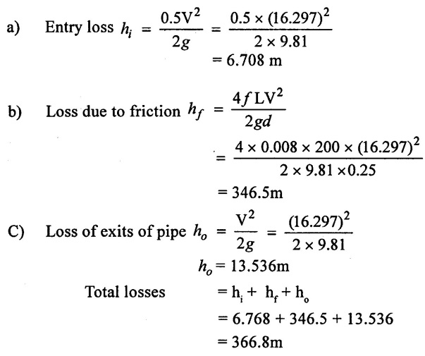
(4) Difference of head in two reservoirs
From equation (i)
H1 = H2 + All losses
H1 = H2 + 366.84
H1 - H2 = 366.84 m
(5) Total energy of various points
a) Total energy at point 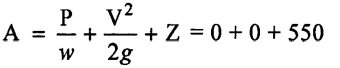
= 550m
b) Total energy at point B Total energy at A - hi
= 550 – 6.768
= 543.22m
c) Total energy at C = H2
H1 = H1 - All loses
= 550 - 366.844
= 183.156m
(6) Steps to draw the total energy line
i) Point D represent the total energy at A
Point E where DE = hi represents total energy at inlet of pipe (hi = 6.768m)
iii) Point F, where CF 183.56m represent the total energy at entrance of outlet reservoir
iv) Join D to E and E to F then DEF represents total energy line
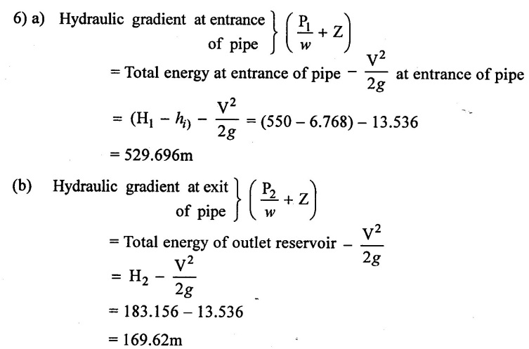
(7) Steps to draw the H.G.L
(i) Piezometric head at the entrance of pipe is 529.6m, so the point G is placed at a distance of 529.69 from the point B on datum line
(ii) Piezometric head at entry of the outlet reservoir is 169.62m, so the point I is placed from the point C at distance of 169.62m
iii) Point G and I are Joined by straight line the line GI represents the HGL
Result:
Distance in elevation between reservoir = 366.84 m
Example - 67
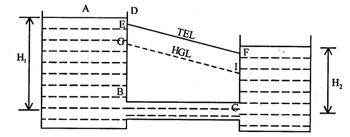
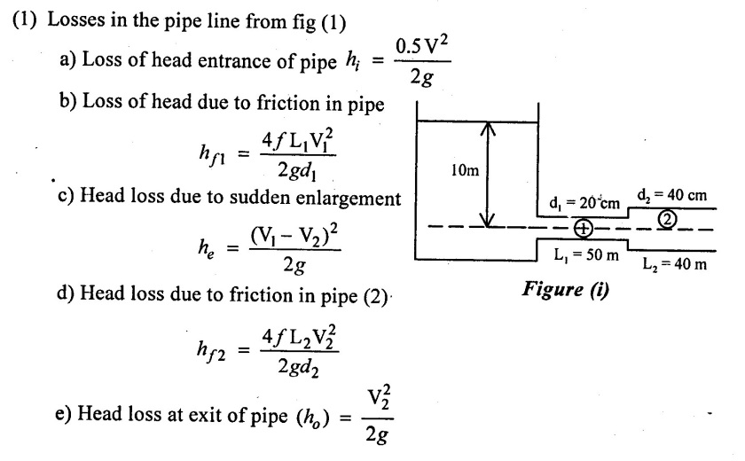
A Horizontal pipe line 90m is connected is connected to a water tank at one end and is open to atmosphere. Fit the 50m length from the tank, the diameter of pipe is 20cm and for remaining length of the pipe is 40cm in diameter. The water level in the tank is 10m above the centre of the pipe take ƒ = 0.006. Consider all the losses. determine discharge through pipe and also Draw HGL and TEL
Given data
Total langth of pipe (L) = 90m
Length of pipe at 1 (L1) = 50m
Length of pipe at 2 (L2) = 40m
Diameter of pipe at 1 (D1) = 20cm = 0.2m
Diameter of pipe at 2 (D2) = 40cm = 0.4m
Water head in tank = 10m
Coefficiend of friction f1 = 0.006
To find
(1) Rate of flow (2) Draw HGL and TEL
Solution
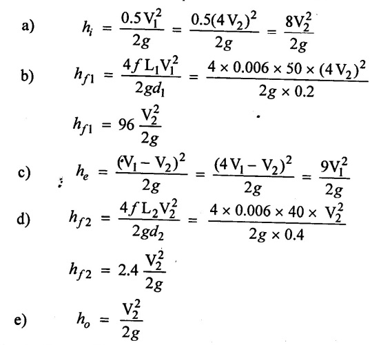
(1) Losses in the pipe line from fig (1)
2) Apply continuity equation
A1 V1 = A2 V2
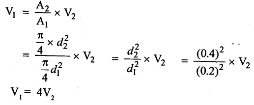
(4) Subtituting the value of V1 in different head loss
(5) Apply Bernoulli's equation
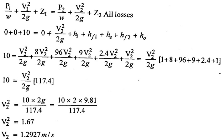
(6) Rate of flow Q = A2 V2
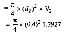
Q = 0.1624 m3/s
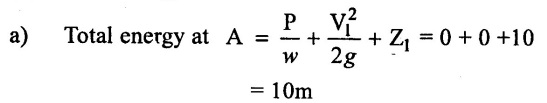
(7) Total energy at various points
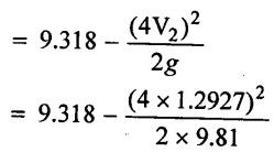
b) Total energy at entrance of pipe at point (B)
= Total energy at A - h1
= 10.8 - 0.6813
= 9.318m
c) Total energy at entrance of pipe (2) at point C before the enlargement
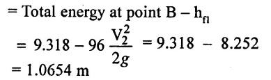
d) Total energy at entrance of pipe (2) at point C after enlargement
= Total energy at entrance of pipe before enlargement – hc
= 1.0654 -0.773
= 0.2924m
e) Total energy at exit of the pipe 2 at point D
= H− [hi + hfi + he + hƒ2]
= 10 [0.6813 + 8.252 + 0.773 + 0.204] = 10 - 9.910
= 0.0897m
8) Steps to draw the Total Energy Line (TEL)
i) The point A is noted on the free surface of water 10m for total head from the datum line.
ii) The total energy available at entrance of pipe (1) is 9.318m. So the point E is noted at a distance 9.318m from the datum line.
iii) Total energy available at entrance of the pipe (2) before the enlargement is 1.0654m. So the point F is noted 1.0654m from datum line.
iv) Total energy available at enlargement of the pipe (2) is 0.647m. So the point G is noted at 0.647m from the datum line.
v) Total energy available at the exit of the pipe is 0.897m. So the point H is noted at 0.897m from the centerline of pipe (or) datum line.
vi) Now joints all the points are available energy levels and get the TEL line of AEFGH.
(9) Steps to draw the Hydraulic Gradient Line (HGL)
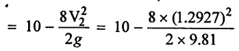
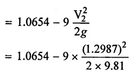
Hydraulic gradient (P/w + z) at entrance of pipe = Total energy available at entrance of pipe –V12/2g
= 7.9522m
ii) Piezometric head at entrance of pipe is 7.9522 m, so the point J is placed at a distance of 7.9522 from the point B of datum line.
iii) A line JK is draw parallel to line EF
iv) Piezometric head at exit of pipe (2) Zero (open to atmosphere), so the point D noted on the centre line of pipe at exit.
v) From D draw,a line DK is draw parallel to GH line.
vi) Now joint the points Land K through straight line then the line JLKD represent the Hydraulic Gradient Line (HGL).

RESULT:
Rate of flow (Q) = 0.1624 m3/s
No comments:
Post a Comment