When a fluid is flowing through a pipe it is observed beyond critical Reynolds number, the laminar flow becomes unstable.
TURBULENT FLOW
When a fluid is flowing through a pipe it is observed beyond critical Reynolds number, the laminar flow becomes unstable. Once instability sets in turbulence in the force of eddies speedy rapidly covering the entire flow region. In turbulant flow, the slow parameters such as pressure and velocity at any point in the flow medium are continuously fluctuating in a random manner. Usually the turbulant flow of fluids consider when pipes running full.
1. Frictional Loss in Pipe Flow.
The fluid flowing in a pipe is always subjected to resistance due to shear forces, between fluid particles and the boundary walls of the pipe. The resistance to the flow of fluid is known as frictional resistance. Due to this resistance there will be always some loss of energy in the direction of flow. That losses are called frictional losses. If is may be completed by Darcy-weisbatch equation.
The frictional resistance for turbulent flow is
(i) Proportional to Vn where n varies from 1.5 to 2.0
(ii) Proportional to the density of fluid.
(iii) Proportional to the area of surface in contact.
(iv) Independent of pressure.
(v) Dependent on the nature of the surface in contact.
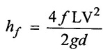
2. Darcy's Weisbatch Equation (or) Expression for Loss of Head Due to Friction in Pipes.
A Frenchman, H.Darcy, was the first to study the " Experimental researches an flow of water in pipes" in 1854. Then Julius weisbatch a German was associated with Darcy to derive the Darcy- weisbatch equation of friction Loss in pipe
Consider a uniform horizontal pipe having steady flow and control volume enclosed between sections.1and 2 of the pipe as shown in figure 2.21.

Let.
P1 = Pressure intensity at section 1-1
V1 = velocity of flow at section 1-1
L = Length of the pipe between sections 1 - 1 and 2 - 2
d = diameter of the pipe
f = frictional resistance per unit wetted area per unit velocity.
hf = loss of head due to friction
P2, V2 = are the values of pressure intensity and velocity at section 2 - 2 respectively.
Applying Bernoulli's equations between two sections.
Total head at 1-1 Total head at 2-2 + Loss of head due to friction between sections 11 to 2-2

The forces acting on the fluid between sections 1 - 1 and 2-2 are, are, Pressure × Area of the pipe.
Pressure force at section 1 − 1 = P1 × A
Similarly,
Pressure force at section 2 -2 = P2 × A
frictional force (F) = frictional Resistance per unit wetted area per unit velocity × wetted area × velocity2
F = ƒ' × лd L × V2 ⸫ Perimeter (P) = πd
= f' × P × L × V2
Resolving all forces acting in the horizantal direction
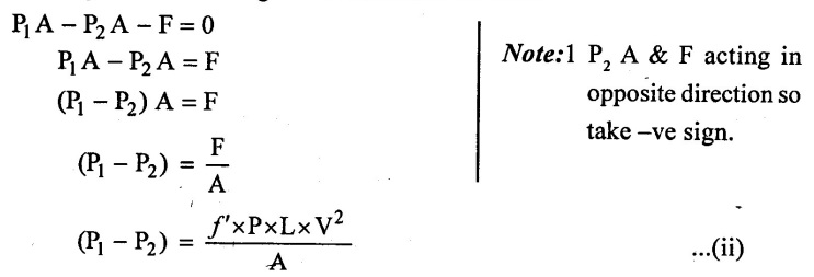
(P1 - P2) value from equation (i) Apply in equation (ii)
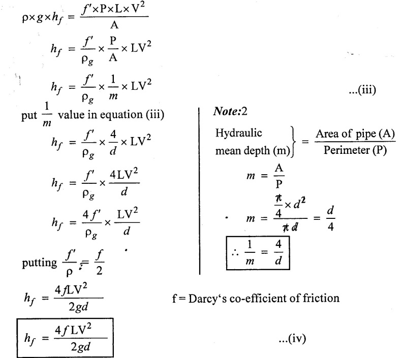
The above equation is called Darcy-weisbatch equation. This equation is commonly used for finding loss of head due to friction in pipe and f is called the Darcy's co-efficient of friction which is dimension less parameter.
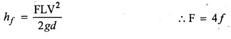
some times the equation (iv) written as
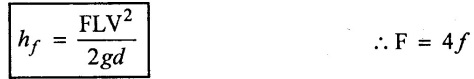
Where, F-Darcy's friction factor
Case (i) If F ≥ 0.02 using the formula
Case (ii) If F ≤ 0.02 using the formula
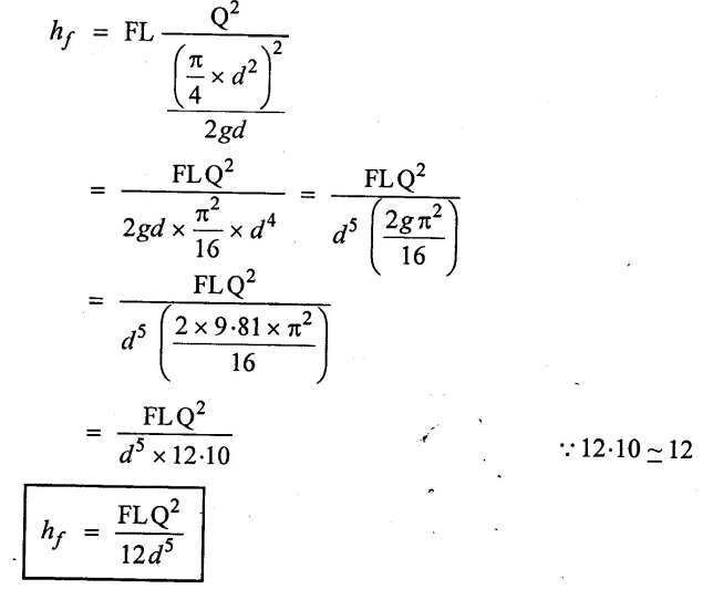
Case (iii) Darcy's formula interms discharge (Q)
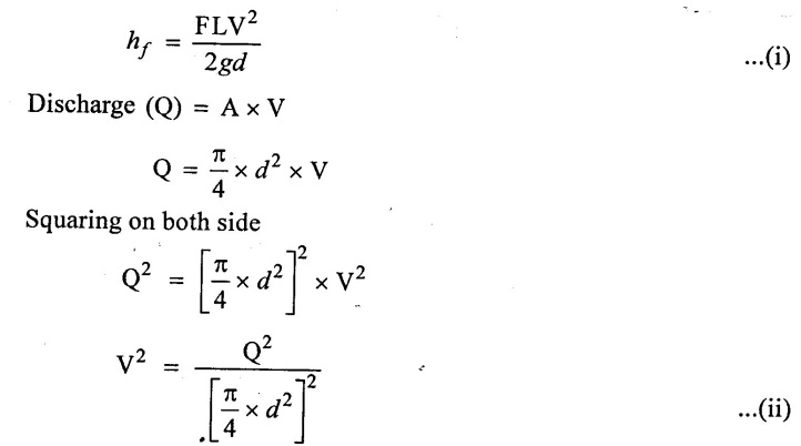
Put the value of Equation (ii) in Equation(i)
3. Friction Factor
It is the dimensional less term. This friction factor (f) is not constant. It is depends upon the following parameters as (i) Reynolds number (ii) the roughness of the pipe surface (k/d)
Where K - Average height of pipe wall roughness protrusions.
d - diameter of the pipe.
In order to determine the loss of head due to friction correctly, It is important to access the value of 'f' correctly.
1. Values of co-efficient of friction for Laminar and turbulent flow.
(i) for Laminar flow (Re < 2000)
(a) co-efficient of friction (ƒ) = 16/Re
(b) friction factor (F) = 16/Re
In the laminar flow co-efficient of friction f is only depends on Reynolds number and not depend on k/d ratio.
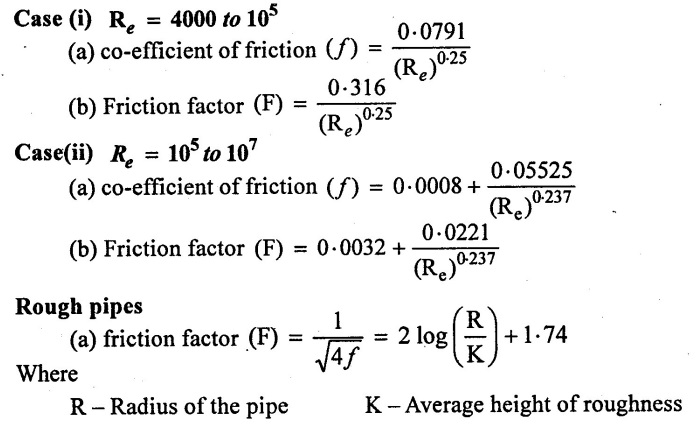
(ii) For Turbulent flow.
The co-efficient of friction for turbulent flow is a function of both Re and k/d ratio. In turbulent flow boundary layer may be smooth (or) rough. So the value of 'f' will be different for these boundaries.
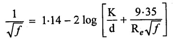
Smooth pipes:
4. Moody Diagram:
The chart developed by C.F. Moody for commercial pipes, become a convenient and more reliable tool for solving practical problems in pipe.
Moody diagram is plotted between various values of friction factor (F), Reynolds number (Re), and relative roughness (k/d) as shown in figure 2.22.
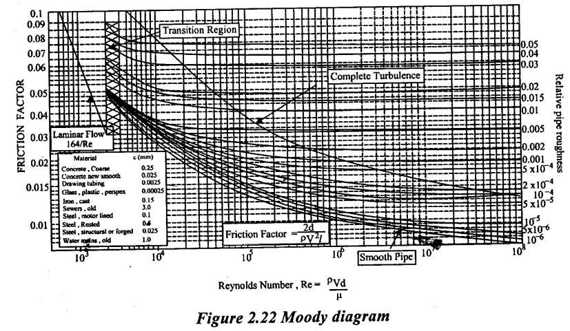
For any turbulent flow problem, The values of friction factor (F) can be determine from moody diagram, If the numerical values of k/d for the pipe and Re of flow are known.
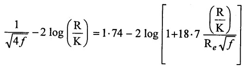
Moody diagram has plotted from the equation for smooth, transition and rough pipes.
Where
K = Average height of roughness
d = diameter of the pipe
Re = Reynolds number
f = friction factor
k/d = Relative pipe roughness.
From moody diagram we can observe the following.
(i) In laminar flow, friction co-efficient (f) is independent of relative roughness and dependent of Reynolds number.
(ii) For Reynolds number greater than 2000, there are two regions one is transition and another one is turbulent region.
(iii) In the transition region friction factor (F) is depends upon the Reynolds number (Re) and relative roughness (K / d).
(iv) In turbulent region friction factor (F) is independent of Reynolds number and depends on pipe relative roughness (K / d).
5. Commercial Pipes
✓ The commercial pipes are made up of metal, concrete and wood.
✓ The size of sand grains when coated to a pipe having same diameter as that of the commercial pipe, gives the same limiting value of friction factor (f) at very large of Reynolds numbers as that of the commercial pipe in natural from, Which is called as Equivalent sand grain roughness.
✓ Equivalent sand grain roughness can be obtained by conducting a series of experiments using different grain size coatings on a pipe till the value of friction factor of grain coated pipe and commercial pipe is same.
Case (i) smooth pipes friction factor.
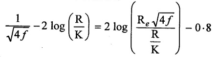
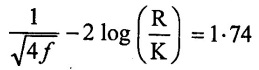
Case (ii) Rough pipes friction factor.
Case (iii) smooth, transition and rough pipe.
The value of equivalent sand grain roughness does not remain constant. For a pipe as it depends upon the conditions of the material of the pipe. A pipe becomes older, the roughness increases due to the corrosion.
6. Solved Examples based on Turbulent Flow Through Pipes
Example - 36
Calculate the head lost due to friction in a pipe of 500 mm diameter and 2.0 Km long, the velocity of flow of water is 3m/s and the friction factor is 0.02 and also find the power required to transfer the fluid.
Given data:
Diameter of pipe (D) = 500 mm = 0.5m
Length of pipe (L) = 2.0 Km = 2000 m
Velocity of flow (V) = 3 m/s
Friction factor (F) = 0.02 (since equal to 0.02)
To find:
(i) Loss of head due to friction (hf)
(ii) Power Required. (p)
Solution:
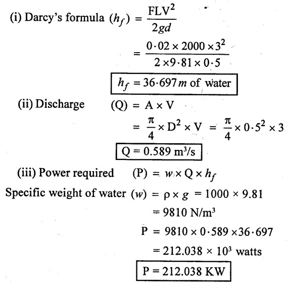
Result:
(i) Loss of head due to friction = 36.697m of water
(ii) Power required = 212.056 KW.
Example - 37
Two reservoirs are connected by a pipe line at length of 400m. The difference in level between the reservoirs is 9m. If the maximum discharge is 0.3 m3/sec. calculate the required size of the pipe and the coefficient of friction f = 0.005.
Given data:
Length of pipe (L) = 400 m
Difference in water level (hf) = 9 m
Discharge (Q) = 0.3m3/sec
Co-efficient of friction (f) = 0.005
To find:
Diameter of pipe (d).
Solution:
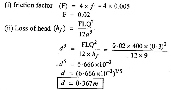
Result:
Diameter of pipe (d) = 0.367 m
Example - 38
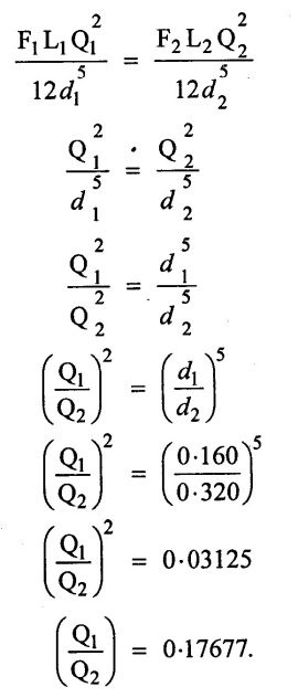
Compare the discharge of 160mm and 320mm diameter pipes when the loss of head due to friction in each pipe is same. consider both pipes to be equal length, and value of f is same for both the pipes.
Given data:
Diameter of pipe - 1 (d1) = 160mm = 0.16m
Diameter of pipe – 2 (d2) = 320mm = 0.32m
Loss of head due to friction is same for both pipes hf1 = hƒ2
Length is same for both pipes. L1 = L2
Value of ƒ is same for both pipes
f1 = f2
Also F1 = F2
To find:
Compare the discharge Q1 / Q2
Solution:
(i) Darcy's formula for pipe - (1)
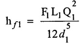
(ii) Darcy's formula for pipe -2
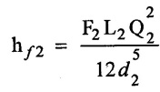
(iii) Loss of head equal for both pipes. so
Result:
Ratio of discharge (Q1 / Q2) = 0.17677.
Example - 39
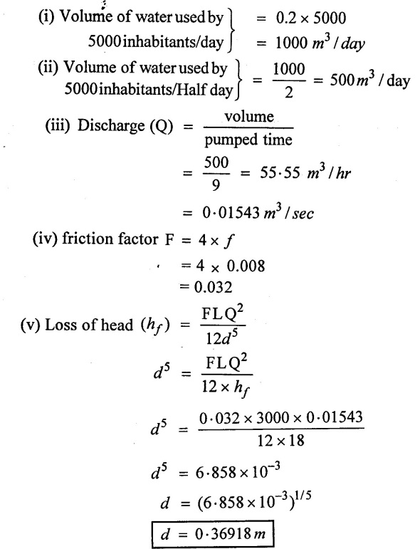
A reservoir has been built 3km away from a college campus having 5000 inhabitants. It is estimated that each inhabitant uses 200 liters of water per day and half of the daily supply is pumped in 9 hours. Calculate the size of the supply main if loss of head due to friction is 18m. co-efficient of friction of the pipe is 0.008.
Given Data:
Volume of water used by one inhabitant = 200 lit/day = 0.20 m3/day
Number of inhabitamts = 5000
Daily supply is pumped = 9 hours
Length of pipe (L) = 3 km = 3000m
Loss of head due to friction (hf) = 18m
Co-efficient of friction (f) = 0.008
To find:
Diameter of pipe (d)
Solution:
Result:
Diameter of pipe (d) = 0.36918 m.
Example - 40
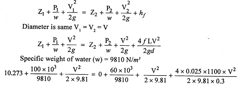
A pipe line 0.3m in diameter and 1100m long has a slope of 1 in 120 for the first 700m and 1 in 90 for the next 400m. The pressure at the upper end of the pipe line is 100 kpa and the lower end is 60 kpa. Taking f=0.025. Determine the discharge through the pipe.
Given data:
Diameter of pipe (D) = 0.3 m
Length of pipe (L) = 1100 m
Slope 1 in 120 for first 700 m
Slope 1 in 90 for remaining 400m
Upper end pressure (P1) = 100 kpa = 100 × 103 N/m2
Lower end pressure (P2) = 60 kpa = 60 × 103 N/m2
Co-efficient of friction (f) = 0.025.
To find:
Discharge (Q)
Solution:
Assume Lower end is datum line and upper end is have datum head and flow is taken from upper end to lower end.
(i) Lower end of datum head (Z2) = 0
(ii) upper end of datum head (Z1) = 
= 5.83 + 4.44 10.273 m
(iii) Apply Bernolli's equation
10.273 + 10.1936 + 0.0509 V2 = 6.116 + 0.0509V2 + 18.688V2
20.466 - 6.116 = 18.739 V2 - 0.0509 V2
14.35 = 18.688 V2
V2 = 0.7679
V = 0.8762 m/s
(iv) Discharge (Q) = A × V
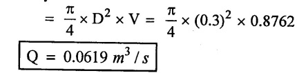
Result:
Discharge (Q) = 0.0619 m3/s
Example - 41
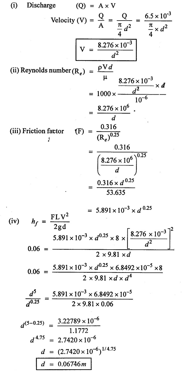
A smooth pipe conveys 6.5 lits/sec of waters with a head loss of 60mm per 8m length. Dynamic viscosity of water is 10-6 Ns/m2 and friction factor  Determine the diameter of pipe.
Given data:
Discharge (Q) = 6.5 lit/sec = 6.5 × 10⁻³ m3/sec
Loss of head (hf) = 60mm = 0.06m
Length of pipe (L) = 8m
Dynamic viscosity of (μ) = 10-6 N.s/m2
Friction factor (F) = 0.316 / (Re)0.25
To find:
Diameter of pipe (d)
Solution:
Result:
Diameter of pipe (d) = 0.06746 m.
Example - 42
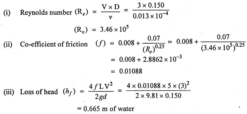
Water is flowing through a pipe of diameter 150mm with a velocity of 3 m/s. If the co-efficient of friction is given by 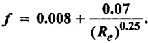 Find the loss of head for length of 5m. Take kinetic viscosity v = 0.013 × 10⁴ m2/sec
Given data:
Pipe diameter (D) = 0.150m
Velocity (v) = 3 m/s
Co- efficient of friction (ƒ) = 0.008 + 0.07 / (Re)0.25
Length of the pipe (L) = 5m
Kinematic viscosity (v) = 0.013 × 10⁻⁴ m2/s
To find:
Loss of heat (hf)
Solution:
Result:
Loss of heat due to friction (hf) = 0.665 m of water.
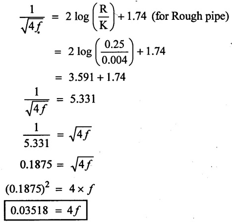
Example - 43
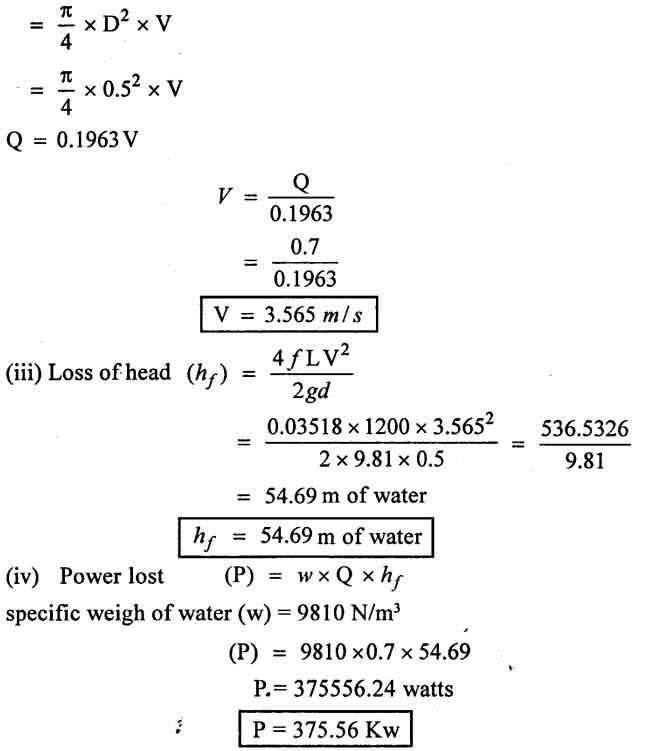
Water is flowing through a rough pipe of diameter 500mm at rate of 700 lit/sec. The wall roughness is 4mm. Find the power lost for 1200m length of pipe.
Given Data:
Diameter of pipe (D) = 500mm = 0.5m.
Radius (R) = 0.25m
Discharge (Q) = 700 lit/sec = 0.7 m3/sec
Wall roughness (K) = 4mm = 0.004m
Length of pipe (L) = 1200m.
To find:
Power Lost (P)
Solution:
(i) Using relation
(ii) Discharge (Q) = A × V
Result:
Power (P) = 375.56 Kw.
Example - 44
The crude oil of specific gravity 0.85 and viscosity 0.3 poise, flows through a smooth pipe of 20cm diameter with average velocity of 4 m/s. calculate the pumping power required to maintain the flow per 2Km length of the smooth pipe.
Given data:
Specific gravity of oil (S) = 0.85
Viscosity of oil (μ) = 0.3 poise = 0.03 Ns/m2
Average velocity (V) = 4 m/s
Diameter of pipe (d) = 20 cm = 0.2m
Length of the pipe (L) = 2Km = 2000m.
To find:
Power lost (P)
Solution:
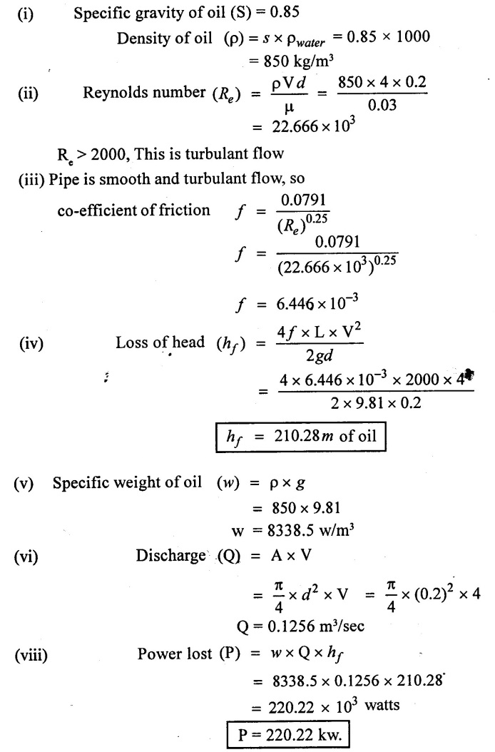
Result:
Power lost (P) = 220.22 kw.
No comments:
Post a Comment