A closed conduit, carrying fluid under pressure is called pipe. The terms pipe and duct are usually used interchangeably for sections.
FLOW THROUGH CIRCULAR CONDUITS
INTRODUCTION
A closed conduit, carrying fluid under pressure is called pipe. The terms pipe and duct are usually used interchangeably for sections. In general flow sections of circular cross-sections are referred to as pipes when the fluid is a liquid and sections of non- circular cross section of ducts when the fluid is a gas. Small diameter pipes are usually referred as tubes.
1. Flow Through Pipe
Pipes are commonly circular in cross-section. As the fluid flows under pressure, it always runs in full. The pressure in a pipe may be above (or) below atmospheric pressure as desired. Most of the liquids are transported in circular pipes because pipes can with stand large pressure differences between the inside and outside without undergoing significant distortion. The fluid flowing is always subjected to resistance due to shear forces between fluid particles, boundary walls of the pipe and between the fluid particles due to the viscosity of the fluid. This resistance is known as frictional resistance- In order to overcome this resistance, certain energy of the flowing fluid is consumed. Thus certain amount of fluid energy is lost due to this resistance. The flow of fluid may be laminar (or) turbulent in the pipe.
2. Reynolds Experiment: Laminar and Turbulent Flow Condition
In 1883, Osborne Reynolds conducted an experiment to demonstrate the type of flow when the fluid flow through the tube
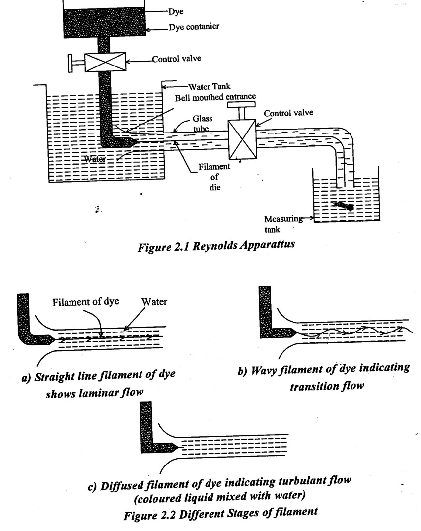
The apparatus designed by Reynolds for his experimental setup consists of:
(i) Water tank is maintained at constant head.
(ii) A small tank containing a coloured liquid having same specific gravity as that of water with dye injection arrangement
(iii) A glass tube having bell mounted entrance connected in the water tank, other end have a valve for controlling flow in glass tube and flow falls in measuring tank.
The general arrangement of the setup is shown in figure 2.1. Reynolds allowed the water to flow through the tube with different mean velocities and maintained constant head by controlling the flow rate in the over head tank. The flow of water from the water tank through the glass tube is now regulated by opening the regulating valve.
Observations made from Experiment:
As long as the velocity in the glass tube is maintained sufficiently low, the colour band remains a thin straight line flowing along the entire length of the glass tube without mixing with water such flow is called laminar flow.
As the velocity of flow in gradually increased a stage is reached when the dye tends to develop a wavy form. This indicates that the laminar flow has become unstable and when dye develops a way form is called transition form (ie.) laminar to turbulent flow.
On further increasing the velocity of flow by opening the regulating valve, the dye starts mixing with surrounding water. This flow is called turbulent flow.
Reynolds from his experiments found that the nature of flow in a closed conduit depends upon the following factors.
(i) Diameter of the pipe (D)
(ii) Density of the liquid (ρ)
(iii) Viscosity of the liquid (μ)
(iv) Velocity of flow(v)
3. Reynolds Number
Reynolds number is the ratio between inertia force to the viscous force. It is a dimension less number.
Reynolds Number (Re) = Inertia force / viscous force = ρVD / μ (or) VD / ν
where
ρ - density of fluids in kg/m3
V - velocity of fluids in m/s
μ - dynamic viscosity of fluids in N-S/m2
v - Kinetic viscosity of fluid in m2/s
D - diameter of the pipe in m.
Reynolds number is used for predicting whether flow is laminar (or) turbulent and finding out the co-efficient of friction (f) in order to determine the loss of head due to friction.
Reynolds number based type of flow.
(i) Re <2000, the flow is laminar
(ii) Re > 4000, the flow is turbulent
(iii) 2000 < Re < 4000 the flow is transition.
4. Critical Reynolds Number
When the flow velocity is slowly increased, a disturbance(or) instability starts to develop in the dye line. The line breaks up into a helical path. Such a fluid flow where in the motions are randomized and irregular represents the turbulent flow, and the velocity at which it initially is called the lower critical Reynolds number.
When the increase in the flow velocity, the dye line breaks completely and the dye gets diffused through out the flow. The flow velocity at this instant is called higher critical velocity and corresponding Reynolds number is higher critical Reynolds number.
The higher critical Reynolds number depends upon following factors.
(i) Initial turbulence in the flow
(ii) Shape of the pipe at entrance
(iii) Roughness of the pipe
5. Laminar flow (or) viscous flow
In laminar flow, the fluid particles move along straight parallel paths in layers. There is no mixing of fluid particles between two adjacent layers.
The shape of the laminar layer depends upon the shape of the boundary through which flow is taking place.
The fluid particles move in un mixing layers (or) streams in smooth continuous path. Laminar flow occurs at low velocity, so that forces due to viscosity are predominant in comparison to inertia forces.
The viscosity of fluid induces relative motion, with in the fluid when layers slide over each other.
The gradient of velocity between the layers give rise to shear stresses. The shear stress in the fluid varies from point to point. It is maximum at the boundary and it gradually decreases with increase in the distance from the boundary.
The shear stresses in between the layers develop a resistance to flow. The pressure of the fluid gradually drops in the direction of the flow. There is always head loss in laminar (or) viscous flow.
1. Conditions of Laminar Flow
(i) Velocity of flow is low.
(ii) Diameter of pipe is small.
(iii) Viscosity of the fluid is high
(iv) Density of the fluid is less.
2. Characteristics of Laminar Flow
(i) No slip at the boundary
(ii) The flow is rotational
(iii) Due to viscosity, there is a shear between fluid layers.
(iv) Loss of energy is proportional to first power of velocity and first power of viscosity.
(v) Reynolds number is always less than the critical value of Pipe flow.
6. Laminar Flow Through a Circular Pipe
(Hagen- poiseuille equation)
The flow through a circular pipe will be viscous (or) laminar, if the Reynolds number is less than 2000.
In laminar flow of flowing fluid, some losses of head take place due to frictional resistance and also viscosity of the fluids. The equation which uses to measure the loss of head due to laminar flow is known as Hagen-poiseuille's equation.
Hagen- poiseuilles equation is based on the following Assumptions.
(i) The fluid follows Newton's law of viscosity
(ii) There is no slip of fluid particles at the boundary
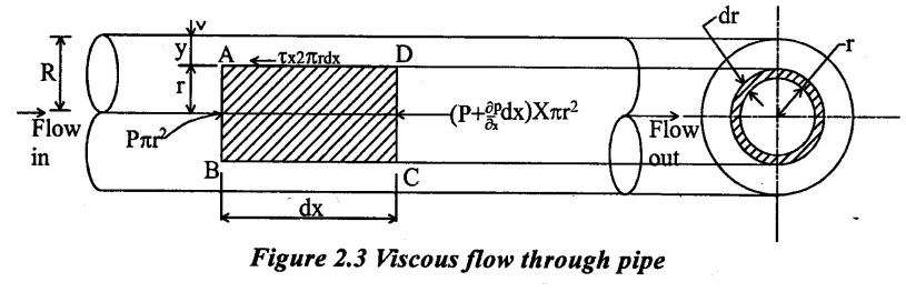
Consider a horizontal pipe of radius (R) and fluid is flowing from left to right in a pipe an shown in figure 2.3.
Consider a fluid element of radius (r), sliding in a cylindrical fluid element of radius (r+dt). Let the fluid element length be dx. If p is the intensity of pressure on the face AB, then the intensity of pressure on the face CD will be 
The forces acting on the fluid element are
(i) The pressure force р × πr2 on face AB
(ii) The pressure force  on face CD
(iii) The shear force, τ × 2 πr dx on the surface of fluid element.
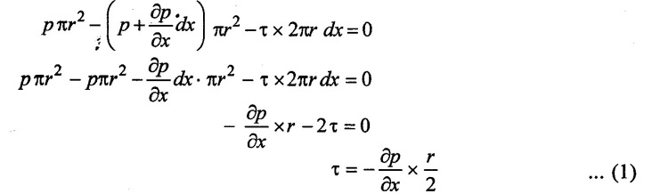
Net forces acting in the direction of flow = mass(m) × acceleration(a)
Fluid flow with very low velocity a=0
As there is no acceleration, hence the summation of all forces in the direction of flow must be zero.
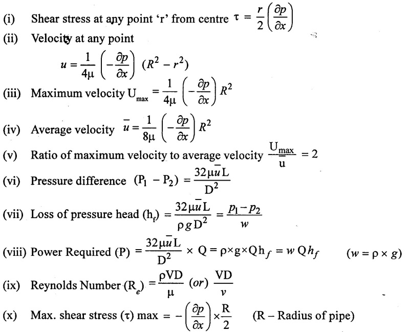
(i) Shear stress and velocity distribution across section
The shear stress τ across a section varies with r as ![]() across a section is constant. Hence shear stress distribution across a section is decreases from wall surface of the pipe to centre of the pipe upto reach the value zero as shown in figure 2.4.
across a section is constant. Hence shear stress distribution across a section is decreases from wall surface of the pipe to centre of the pipe upto reach the value zero as shown in figure 2.4.
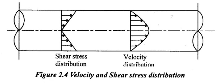
The velocity distribution across a section is increased from wall surface to the centre of the pipe upto it reaches maximum value as shown in figure 2.4.
The velocity distribution across a section can be obtained by equating Newton's law of viscosity.
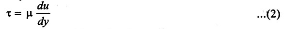
Where y is measured from the pipe wall
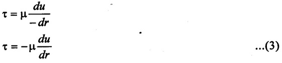
y = R - r
Differentiating this equation with respect to r, we get,

dy = - dr
the dy value apply in equation (2)
the value of τ from equation (1) apply in equation (3)
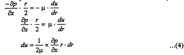
the equation (4) integrating with respect to r

Where C is the constant of integration and value is obtained from the boundary condition.
At r = R, u = 0 (Assume as fixed surface)
The boundary condition apply in equation.(5)
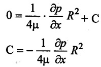
the C value apply in equation (5)
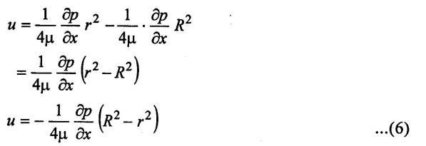
In the equation (6) μ, ![]() , R are constant, which means the velocity u varies with the square of r, thus equation (6) is a equation of parabola. This shows that the velocity distribution across the section of a pipe is parabolic. This velocity distribution is shown Figure 2.4.
, R are constant, which means the velocity u varies with the square of r, thus equation (6) is a equation of parabola. This shows that the velocity distribution across the section of a pipe is parabolic. This velocity distribution is shown Figure 2.4.
(ii) Ratio of maximum velocity (Umax) to average velocity. (u)
The velocity is maximum, when r = 0, u = Umax
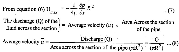
The discharge (Q) area across the section is obtained by considering the flow through a circular ring element of radius (r) and thickness (dt) as shown in figure 2.3 the fluid flowing per second through this elementary ring.
dQ = velocity at a radius (r) x area of the ring element
= u × 2πr dr

Ratio of Maximum velocity to Average velocity = 2.0
(iii) Drop of pressure for a given length (L) of a pipe
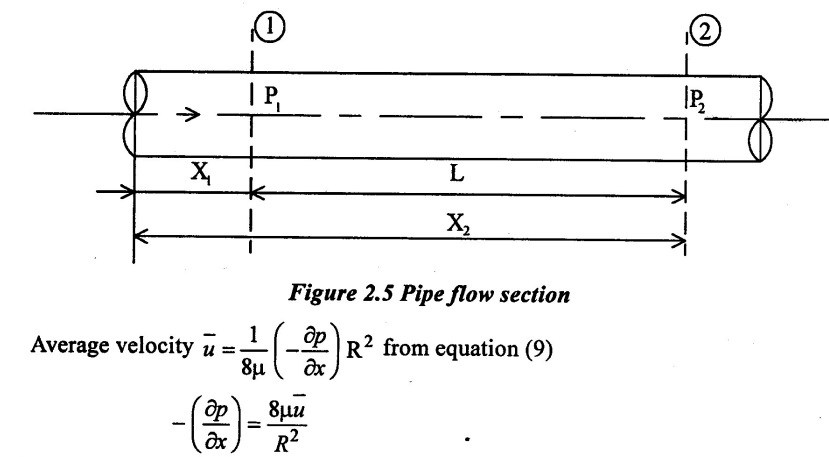
Integrating above equation with respect to x.
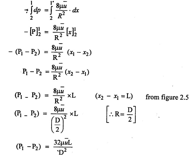
P1 - P2 -> is the drop of pressure
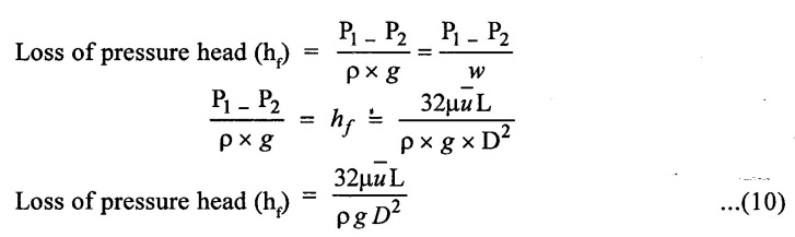
The above equation is called Hagen poiseuille equation.
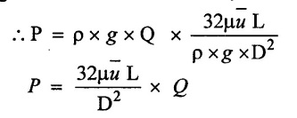
(iv) Power required to overcome viscous resistance
power (p) = Weight of oil flowing per sec × Head loss = w × hf
Weight of oil per second w = ρ × g × Q
7. Solved Examples based on Laminar Flow through Pipes and Formula Used
Example-1
A fluid of viscosity 0.72 N-s/m2 and specific gravity 1.34 is flowing through a circular pipe of diameter 100 mm. The maximum shear stress at the pipe wall is given as 200N/m2. Find (i) pressure gradient (ii) Average velocity and (iii) Reynolds number of the flow.
Given Data:
Fluid viscosity (μ) = 0. 72 N-s/m2
Specific gravity (S) = 1.34
Pipe diameter (D) = 100 mm 0.1m
Maximum shear stress (τmax) = 200 N/m2
To find:
(i) Pressure Gradient 
(ii) Average velocity (![]() )
)
(iii) Reynolds Number (Re)
Solution:

Result:
(i) Pressure Gradient = 8000 N/m2 perm
(ii) Average velocity (![]() ) 3.472 m/s
) 3.472 m/s
(iii) Reynolds Numbers (Re) = 646.2
Example - 2
Show that for viscous flow through a circular pipe mean velocity of flow at a radial distance of 0.707 R from the centre of pipe when R is the radius of pipe.
Solution:

Hence proved.
Example - 3
A Lubricating oil of viscosity 0.1 N-s/m2 and specific gravity 0.8 is pumped through a 60 mm diameter pipe. if the pressure gradient per meter of pipe is 26 KN/m2, find the Rate of flow.
Given Data:
Viscosity of oil (μ) = 0.1 NS/m2
Specific Gravity of oil (S) = 0.8
Pipe diameter (D) = 60 mm = 0.06m
Pressure drop (or) pressure gradient = = 26 KN/m2
= 26 × 103 N/m2
To find:
Rate of flow (Q)
Solution:

Result:
Discharge (Q) = 0.0827 m3/sec
Example - 4
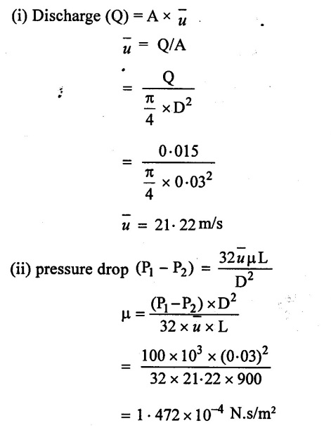
Oil having specific gravity of 0.92 is pumped through a 30 mm diameter pipe. The discharge is 0.90 m3/min, and pressure drop is 100 Kpa for 900 m length of pipe. Find viscosity of oil.
Given data:
Specific Gravity of oil (S) = 0.92
Diameter of pipe (D) = 30 mm = 0.03 m
Discharge (Q) = 0.9 m3/min = 0.015 m3/sec
pressure drop (P1 – P2) = 100 Kpa = 100 KN/m2 = 100 × 103 N/m2
Length of the pipe (L) = 900 m.
To find:
Viscosity of oil (μ)
Solution:
Result:
Viscosity of oil (μ) = 1.472 × 10⁻⁴ N.s/m2.
Example - 5
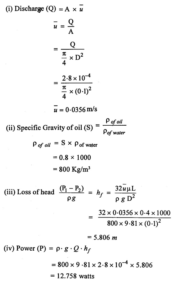
A Viscous flow is taking place in a pipe of 10cm diameter with discharge of 2.8 × 10⁴ m3/s. what power per Kilometer is required to maintain the flow and viscosity of oil is 0.4 Ns/m2. Take specific gravity of oil is 0.8 and length of the pipe is 1Km.
Given data:
Pipe diameter (D) = 10 cm = 0.1m
Discharge (Q) = 2.8 × 10⁻⁴ m3/s
Viscosity of oil (μ) = 0.4 Ns/m2
Specific Gravity of oil (S) = 0.8
Length of pipe (L) = 1Km = 1000m
To find:
Power required per Kilometer (P)
Solution:
Result:
Power (P) = 12.758 watts
Example - 6
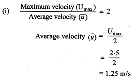
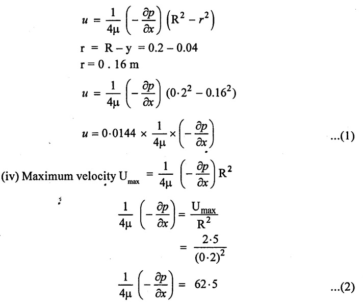
A Laminar flow is taking place in a pipe of diameter 0.4m. The maximum velocity is 2.5 m/s. Find the mean velocity and the radius at which occurs. Also calculate the velocity of 0.04m from the wall pipe.
Given data:
Diameter of the pipe (D) = 0.4m
Maximum velocity Umax = 2.5 m/s
Distance from the wall pipe (y) = 0.04m.
To find:
(i) Mean velocity (or) Average velocity ![]()
(ii) Velocity at the distance y = 0.04m
Solution:
(ii) Average velocity occurs at radius (r) = 0.707 R (Constant value)

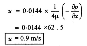
(iii) velocity at 0.04 from pipe wall. (y = 0.04m)
apply the value of equation (2) in equation (1)
Result:
(i) Average velocity ![]() = 1.25 m/s
= 1.25 m/s
(ii) Average velocity occurs at radius (r) = 0.1414 m.
(iii) velocity at 0.04m from pipe wall (u) = 0.9 m/sec
Example - 7
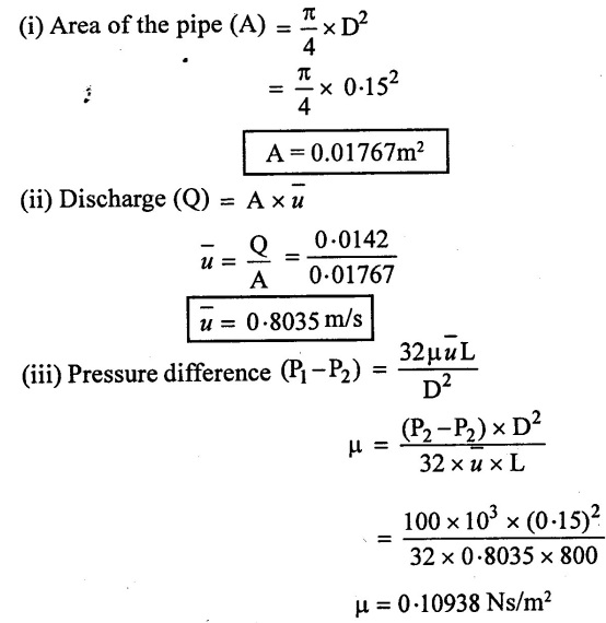
An oil of density 917 kg/m3 is being pumped in à 15cm diameter pipe. The discharge is measured as 850 l/min. The drop in pressure in a stretch of 800m of pipe line, both ends of which are at the same elevation is measured as 100 Kpa. Estimate the absolute viscosity of the oil.
Given data:
Density of oil (ρ) = 917Kg/m3
Diameter of pipe (D)= 15 cm = 0.15 m
Discharge (Q) = 850 l/min = 0.0142 m3/sec
Length of pipe (L) = 800m.
pressure drop (P1 - P2) = 100 Kpa = 100 × 103 N/m2
To find:
Absolute viscosity of oil (μ)
Solution:
Result
Absolute viscosity of oil (μ) = 0.10938 Ns/m2
Example - 8
Crude oil relative Density of 0.8 is pumped through a smooth horizontal pipe 400m long, 200mm diameter. Kinematic viscosity of oil is 3.2 stokes. Differential pressure head between two ends of the pipe is 15.02m of oil. Assuming the flow of oil is to be laminar, find
(i) Rate of flow of oil through pipe
(ii) Power required to maintain the flow.
Also check whether the flow is actually laminar (or) not.
Given Data:
Relative Density (S) = 0.8
Length of the pipe (L) = 400m
Diameter of pipe (D) = 200mm = 0.2m
Kinematic viscosity of oil (μ) = 3.2 stokes = 3.2 × 10⁻⁴ m2/s
Pressure head  = hƒ = 15.02m
To find:
(i) Rate of flow of oil
(ii) Power required to maintain
(iii) Check the flow is laminar (or) not
Solution:

The Actual flow is Laminar
Result
(i) Rate of flow (Q) = 0.04517 m3/s
(ii) Power (P) = 53 24. 50 watts
(iii) The Actual flow is Laminar
Example - 9
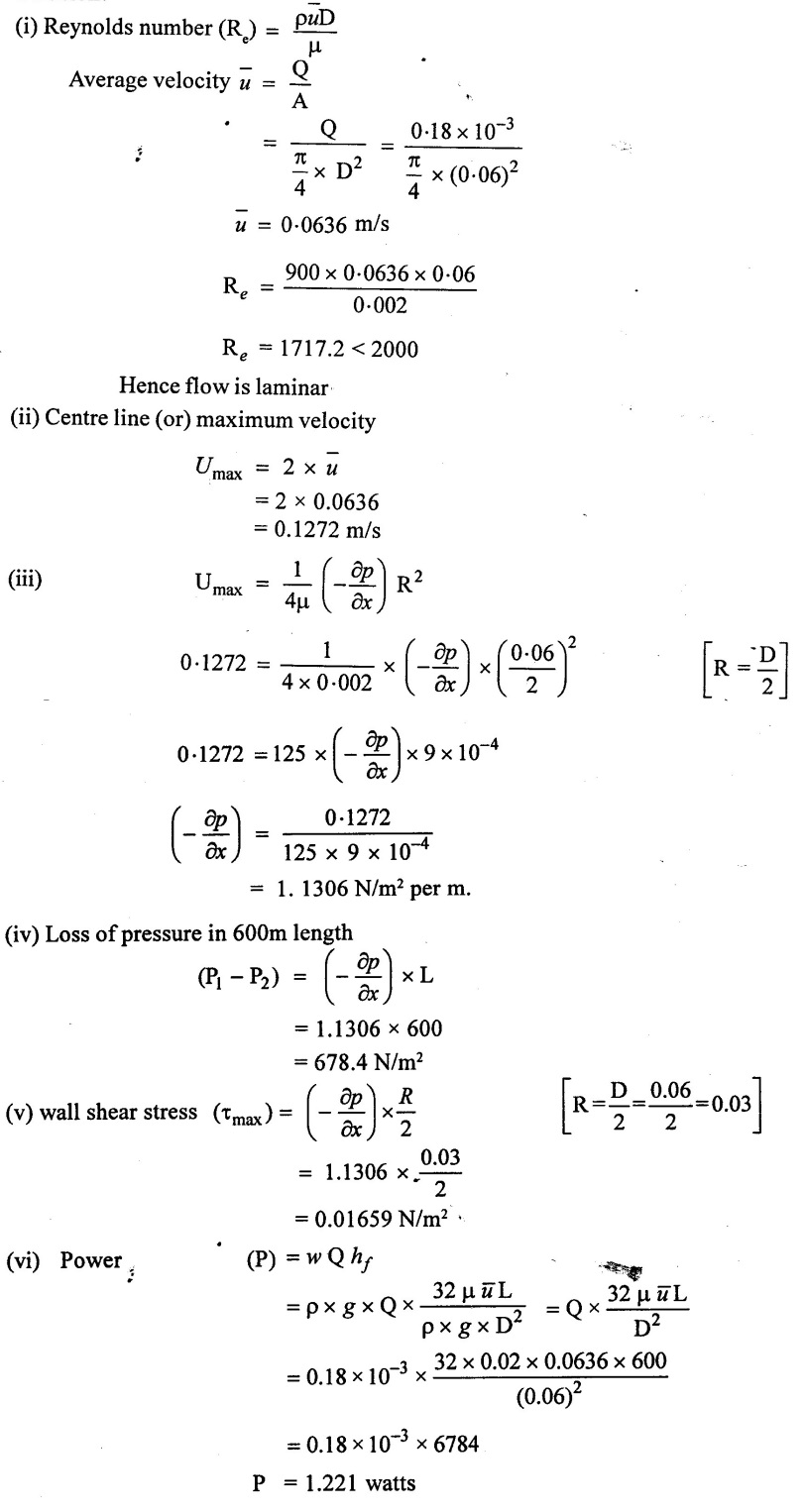
Oil of mass density 900kg/m3 and dynamic viscosity 0.02 poise flow through 60mm diameter pipe of length 600mm at the rate of 0.18 LPS. Determine
(i) Reynolds Number
(ii) Centre line velocity
(iii) Pressure gradient
(iv) Loss of pressure in 600m length
(v) Wall shear
(iv) Power required to maintain the flow.
Given data:
Density of oil (ρ) = 900 kg/m3
Dynamic viscosity (μ) = 0.02 poise = 0.002 Ns/m3
Pipe diameter (D) = 60mm = 0.06m
Length of pipe (L) = 600m.
Rate of flow (Q) = 0.18 lps = 0.18 ×10⁻³ m3/s
To find :

Solution:
Result:
Reynolds Number (Re) = 1717.2
Centre line velocity (Umax) = 0.1272 m/s
Pressure gradient  = 1.1306 N/m2 per m
Loss of pressure (P1 - P2) = 678.4 N/m2
Wall shear stress (τmax) = 0.016959 N/m2
Power (P) = 1.221 watts.
Example - 10
A crude oil Viscosity of 0.8 poise and relative density 0.93 is flowing through a horizontal circular pipe of diameter 200mm and of length 15m. Calculate the difference of pressure at the two ends of pipe, if 120 kg of the oil is collected in a tanks in 40 seconds.
Given data:
Viscosity of oil (μ) = 0.8 poise.
= 0.08 Ns/m2
Relative density (or) specific gravity (S) = 0.93
Diameter of the pipe (D) =200mm = 0.2m
Length of the pipe(L) =15m
Mass of the oil collected (m) = 120kg
time (t) = 40 sec
To find:
Pressure difference (P1 - P2)
Solution:

Result:
Pressure difference (P1 - P2) = 98.496 N/m2
Example - 11
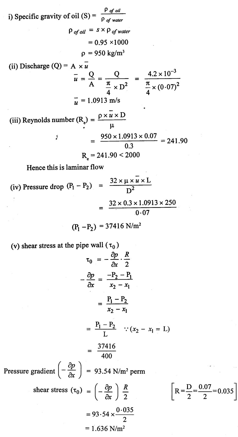
An oil of viscosity 0.3 Ns/m2 and specific gravity 0.95 is flowing through a pipe of diameter 70mm and of length 400m. The rate of flow through the pipe is 4.2 lit/sec, find the pressure drop in a length of 250m and also shear stress at the pipe wall.
Given data:
Viscosity of oil (μ) = 0.3 Ns/m2
Specific Gravity of oil (S) = 0.95
Diameter of pipe (D) = 70 mm = 0.07m
Length of pipe (L) = 400m.
Rate of flow (Q) = 4.2 lit/sec = 4.2 × 10⁻³ m3/sec
To find:
(i) Pressure drop in a pipe length of 250m
(ii) shear stress at the pipe wall (τ0)
Solution:
Result:
(i) Pressure drop (P1 − P2) = 37416 N/m2
(ii) shear stress at the pipe wall (τ0) = 1.636 N/m2
Example - 12
An oil of viscosity 7 poise and density of oil is 930 kg/m3 is flowing through a horizontal pipe of 50mm diameter, if the pressure drop is 200m length of pipe is 2500 KN/m2. Determine
(i) Rate of flow of oil
(ii) Centre line velocity
(iii) Total frictional drag
(iv) Power required to maintain the flow
(v) velocity gradient at the pipe wall
(vi) velocity and shear stress at 9mm from the wall
Given Data:
Viscosity of oil (μ) = 0.7 Ns/m2
Density of oil (ρ) = 930 kg/m3
Diameter of pipe (D) = 50mm = 0.05m
Length of pipe (L) = 200m
Pressure drop (P1 - P2) = 2500 KN/m2 = 2500× 103 N/m2
To find:
(i) Rate of flow of oil (Q)
(ii) Centre line velocity (Umax)
(iii) Total frictional drag force (FD)
(iv) Power required to maintain the flow (P)
(v) velocity gradient at pipe wall 
(vi) velocity and shear stress at 9mm from the wall.
Solution:

(b) shear stress distribution
Result:
(i) Rate of flow (Q) = 2.739 × 10⁻³ m3/s
(ii) Centre line velocity (Umax) = 2.79 m/s
(iii) Total frictional drag force (FD) = 9817.47 N
(iv) Power required (P) = 6.847 kw
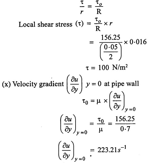
(v) Velocity gradient  = 223.21 s-1
(vi) velocity and shear stress at 9mm from the pipe wall
u = 1.647 m/s & (τ) = 100 N/m2
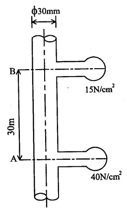
Example - 13
Crude oil of μ = 2 poise and density 900 kg/m3 flows through a 30 mm diameter vertical pipe. The pressure gauges fixed at 30m apart read 40 N/cm2 and 15 N/cm2 as shown in figure. Find the direction and rate of flow through pipe.
Given Data:
Viscosity of oil (μ) = 2 poise = 0.2 Ns/m2
Density of oil (ρ) = 900 kg/m3
Diameter of pipe (D) = 30 mm
Pressure at point A (PA) = 40 N/cm2 = 40 ×104 N/m2
Pressure at point B(PB) = 15 N/cm2 = 15 ×104 N/m2
To find:
(i) Direction of flow
(ii) Rate of flow
Solution:

Result:
(i) Direction of flow from B to A
(ii) Rate of flow (Q) = 4.94 x 10⁻⁵ m3/s
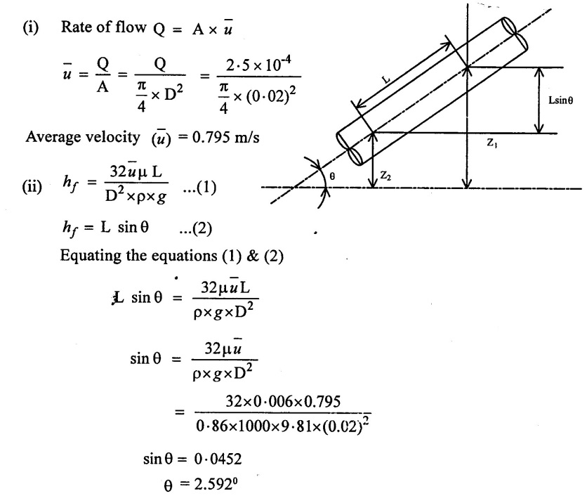
Example - 14
A liquid of viscosity 0.06 poise and relative density 0.86 flows through an inclined pipe of 20mm diameter. A discharge of 0.015m3/min. is to be maintain through the pipe in such a way that pressure along the length is constant. Find the required inclination of the pipe.
Given Data:
Viscosity (μ) = 0.06 poise = 0.006 Ns/m2
Relative density (S) = 0.86
Pipe diameter(D) = 20mm = 0.02m
Discharge (Q) = 0.015 m3/min
= 2.5 ×10⁻⁴ m3/sec
To find:
Required Inclination of pipe
Solution:
Assume the flow has to take from higher Level to lower. So that loss of head due to friction is equal to static head due to difference of levels for length L.
so hƒ = (Z1 − Z2) = L sin θ
Result:
Required inclination of pipe θ = 2.592°
Example - 15
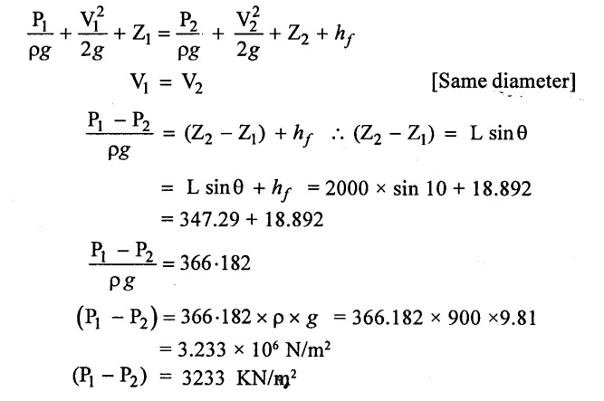
An Inclined pipe of inclination 10o with the horizontal is 2.0 km long and carries oil of specific gravity 0.9. The flow rate of oil being 70 LPS. If the dynamic viscosity of oil is 4.4 poise. Determine the difference of pressure at the two ends. The diameter of the pipe line is 35 cm.
Given data:
Inclination of pipe θ = 10°
Length of the pipe (L) = 2 km = 2000 m
Specific gravity of oil (S) = 0.9
Rate of flow (Q) = 70 LPS = 70 ×10-3 m3/s
Dynamic viscosity (μ) = 4.4 poise = 0.44 N-s/m2
Diameter of pipe (D) = 35 cm = 0.35m
To find:
Pressure difference (P1 – P2)
Solution:

(v) Apply Bernoulli's equation
Result:
Pressure difference (P1 - P2) = (P1 - P2) = 3233 KN/m2
Example -16
An oil of specific gravity 0.90 and kinematic viscosity 20×10-6 m2/s flows in a smooth pipe of 10cm diameter at rate of 140 lit/min. Determine whether the flow is laminar (or) turbulent. Also calculate the velocity at the centre line and velocity at a radius of 3cm.
(i) What is head loss for a length of 11m.?
(ii) What will be the entry length? Also determine the wall shear.
Given data:
Specific gravity of oil (S) = 0.90
Kinematic viscosity (v) = 20 ×10-6 m2/s
Pipe diameter (D) = 10 cm = 0.1m
Pipe Radius (R) = D/2 = 0.1/2 = 0.05m
Rate of flow (Q) = 140 lit/min = 140 × 10-3 m3/min
= 2.333 ×10⁻³ m3/sec
To find:
(i) Type of flow
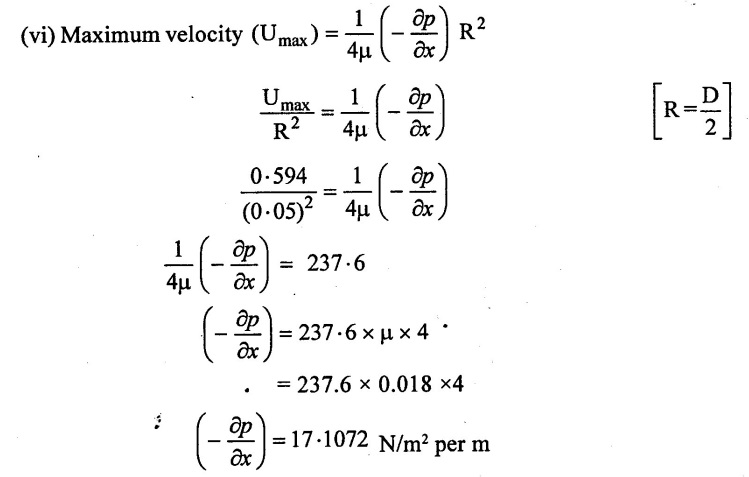
(ii) Centre line (or) Max. velocity (Umax)
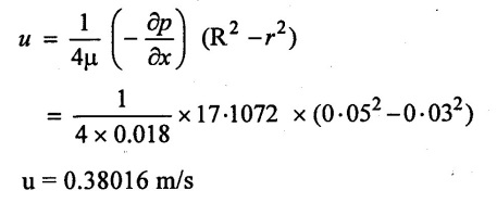
(iii) Velocity at a radius of 3cm
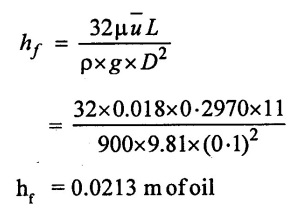
(iv) Head loss for a length 11 m
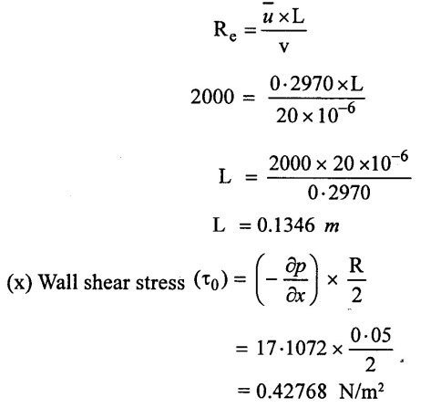
(v) Entry length (laminar flow)
(iv) wall shear stress (τ0)
Solution:

μ = ν × ρ
= 20 ×10-6 × 900
Dynamic viscosity (μ) = 0.018 Ns/m2
(vii) Velocity at radius 3 cm from the pipe wall (u)
(viii) Loss of head at L = 11m.
(ix) Entry length of Laminar flow
Max. limits of laminar flow Re = 2000 [For closed pipe]
Result:
(i) Type of flow is laminar
(ii) Maximum velocity (Umax) = 0.594 m/s
(iii) Velocity at a radius 3 cm = 0.38016 m/s
(iv) Loss of head for a length (L=11 m) = 0.0213 m of oil
(v) Entry length for Laminar flow = 0.1346 m
(vi) Wall shear stress (τ0) = 0.42768 N/m2
Example - 17
Oil at 27° C [ρ = 850 kg/m3 and μ = 35 centi poise] is flowing steadily in a 1.35 cm diameter, 50 m long pipe. During the flow, the pressure at the pipe inlet and exit is measured to be 7 bar and 1 bar respectively. Determine the flow rate of oil through the pipe when
(i) Horizontal (ii) Inclined 15° upward.
(iii) Inclined 15° downward (iv) vertical.
Given data:
Density of oil (ρ) = 850 kg/m3
Dynamic viscosity of oil (μ) = 35 centipoise = 0.35 poise = 0.035 N.s/m2
Diameter of pipe (D) = 1.35 cm = 0.0135 m
Length of pipe (L) = 50 m
Inlet pressure (P1) = 7 bar = 7 × 10⁵ N/m2
outlet pressure (P2) = 1bar = 1 × 10⁵ N/m2
To find:
Rate of flow for following cases.
(i) Horizontal
(ii) Inclined 15° upward.
(iii) Inclined 15° down wards.
(iv) vertical.
Solution:

Diameter is same hence v1 - v2
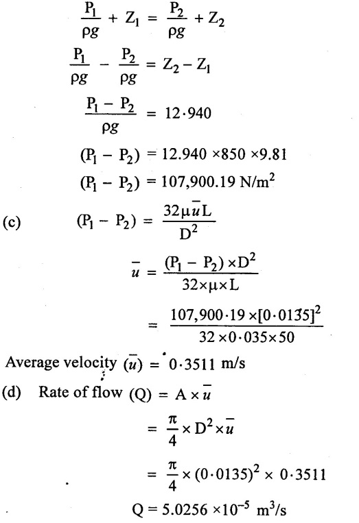
Case (iii) pipe is inclined at 15° downwards.
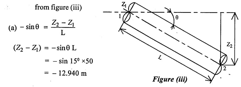
(b) Similarity above case pressure drop (P1 - P2) = (Z2 − Z1) × ρ × g
(P1 - P2) = 850 × 9.81 (-12.940)
= - 107900.19 N/m2
(c) Flow rate is same when the pipe is downwards and opposite direction
Q = - 5.0256 ×10⁻⁵ m3/sec
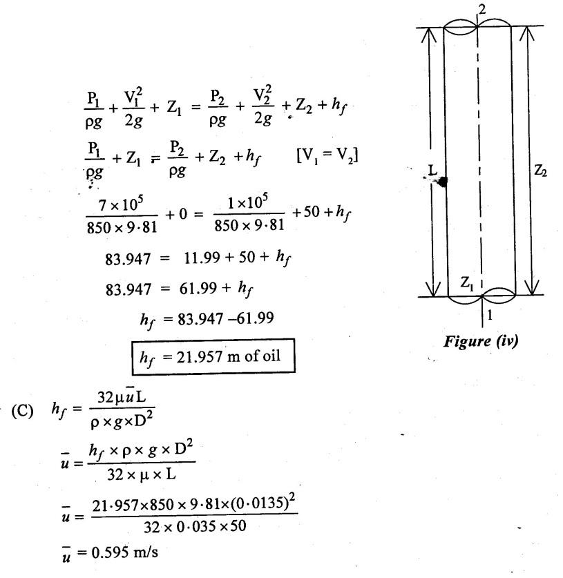
Case (iv) pipe is vertical.
(a) From figure (iv)
Z1 = 0
Z2 = 50 m
(b) Apply Bernoullis equation
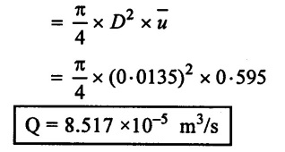
 (d) Rate of flow (Q) = A ×
 ![]()
Result:
Rate of flow
(i) When pipe is Horizontal (Q) = 2.795 × 10⁻⁴ m3/sec
(ii) When pipe is inclined upward at 15° (Q) = 5.0256 × 10⁻⁵ m3/s.
(iii) When pipe is inclined downward at 15° (Q) = - 5.0256 × 10⁻⁵ m3/s
(iv) when pipe is vertical (Q) = 8.517 × 10⁻⁵ m3/sec
No comments:
Post a Comment