The tensile test is one of the most widely used of the mechanical tests.
TENSILE TEST
✔ The tensile test is one of the most widely used of the mechanical tests.
✔ A tensile test of a material is performed on ductile materials to determine tensile properties such as:
(i) Limit of proportionality,
(ii) Yield point or yield strength,
(iii) Maximum tensile strength,
(iv) Breaking strength,
(v) Percentage elongation,
(vi) Percentage reduction in area, and
(vii) Modulus of elasticity.
✔ The tensile test is usually carried out with the help of a 'Universal Testing Machine' (UTM).
1. Arrangement
✔ The material to be tested, also known as a specimen, is machined to standardised dimensions, as shown in Fig.5.13. A typical specimen has a diameter of 12.5 mm and a gauge length of 50 mm.

✔ A schematic working arrangement of a universal testing machine is shown in Fig.5.14.

The specimen is elongated by the moving cross head; load cell and extensometer measure the magnitude of the applied load and the elongation respectively.
2. Testing Procedure
The specimen to be tested is fastened to the two end-jaws of the UTM. Now the load is applied gradually on the specimen by means of the movable cross head, till the specimen fractures.
During the test, the magnitude of the load is measured by the load measuring unit (load cell). A strain gauge or extensometer is used to measure the elongation of the specimen between the gauge marks when the load is applied.
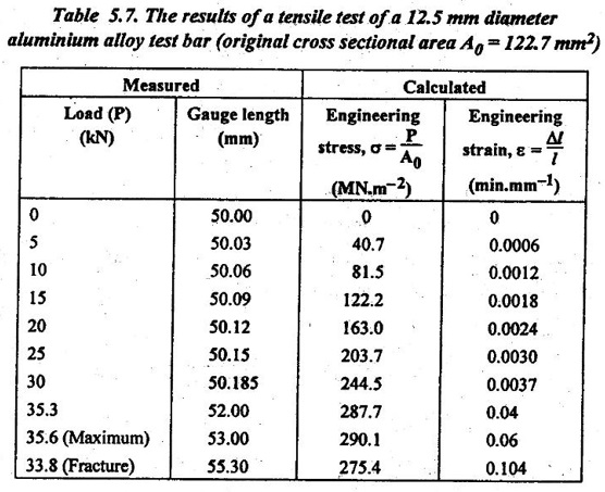
Then the different values of load and elongation at different intervals are recorded and tabulated, as shown in Table 5.7.
3. Stress-Strain Curve
By using the Table 5.7, the stress-strain curve can be plotted as shown in Fig.5.15.

4. Results of Tensile Test (Calculation of Tensile Properties)
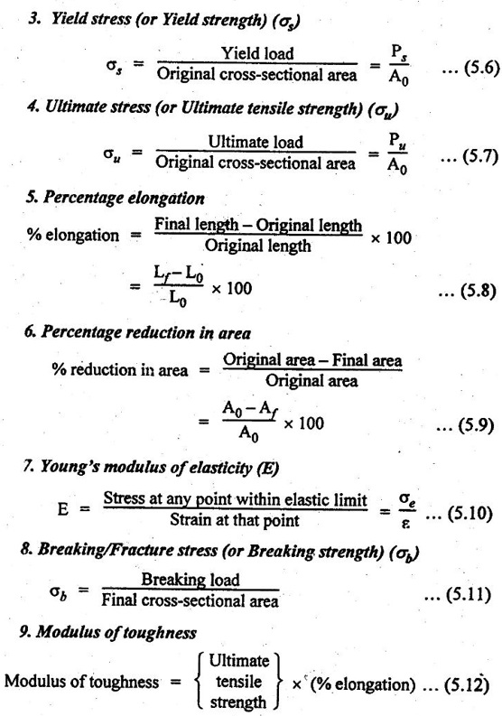
The various tensile properties are calculated, with the help of stress-strain curve, using the following relations :
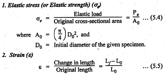
where Lo and Lf represent the initial and final gauge lengths respectively.
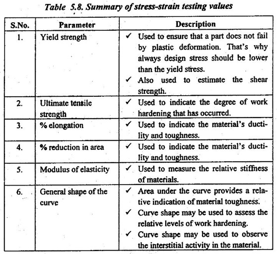
5. Significance of Tensile Testing
Table 5.8 summarises the basic parameters and their significance obtained from tensile testing.
6. Illustrative Problems on Tensile Test
Example 5.1
A steel specimen is tested in a standard tension test to evaluate several mechanical properties. The dimensions of the specimen and observations made during the test are given below:
Diameter of the specimen = 12.5 mm
Gauge length = 62.5 mm
Load at yield point = 41 kN
Maximum load = 72.5 kN
Fracture load = 51.25 kN
Gauge length at fracture = 80.5 mm
Diameter of fracture section = 9.5 mm
Strain at a load of 20 kN = 7.764 x 10⁻⁴ mm/mm
Determine:
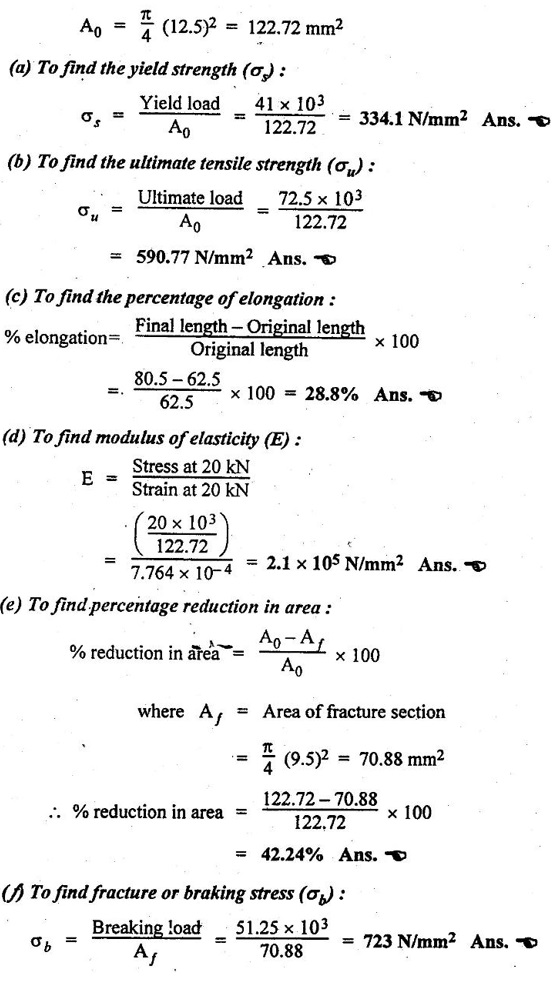
(a) The yield strength,
(b) The ultimate tensile strength,
(c) The % elongation,
(d) Modulus of elasticity,
(e) % reduction in area, and
(f) Fracture stress, and
(g) Modulus of toughness.
● Solution:
The original area of cross-section,
(g) To find the modulus of toughness :
Modulus of toughness = Ultimate tensile strength × % elongation
= 590.77 × 0.288
= 170.14 N/mm2 Ans.![]()
Example 5.2
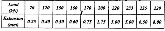
The following date were obtained in a tensile test on a specimen of 15 mm diameter with a 50 mm gauge length :
The specimen diameter after fracture was 12.45 mm.
Determine:
(i) tensile strength; (ii) Young's modulus; (iii) 0.2% proof stress ; (iv) % elongation, and (v) % reduction in area.
● Solution:
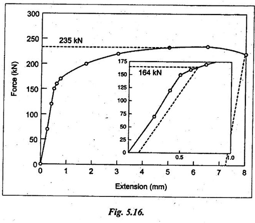
Using the given load and extension data table, a load- extension diagram is plotted as shown in Fig.5.16.
Cross-sectional area of test piece, A0 = π/4 (15)2 = 176.7 mm2
(i) To find the tensile strength :
From graph plot maximum force = 235 kN
Tensile strength = 235 × 103 / 176.7
= 1330 N/mm2 Ans.![]()
(ii) To find the Young's modulus: From graph,
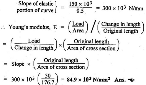
(iii) To find 0.2% proof stress:
Proof stress is the level of stress required to produce small amount of plastic deformation.
0.2% of proof stress = 0.2% of 50 mm = 0.1 mm
Now draw a line parallel to the linear portion of curve from an extension of 0.1 mm, as shown in Fig.5.16. This cuts the curve at a load of 164 kN.
⸫ 0.2% proof stress = 164 × 103 / 176.7
= 928 N/mm2 Ans.![]()
(iv) To find % elongation:
On the force-extension curve draw a line from the fracture point, parallel to the linear elastic portion. This cuts the X-axis at an extension of 7.3 mm.
% elongation on a 50 mm gauge length = 7.3 / 50 × 100
= 14.6% Ans.![]()
(v) To find % reduction in area :
Diameter after fracture, Df = 12.45 mm

= 31.1% Ans.![]()
No comments:
Post a Comment