In earlier stages of IC engines, Engine Valve was based on steam engines and used slide valves. In 1876 the first successful otto engine also used the slide valve.
It was later in the 1950s when poppet valves started becoming common in internal combustion engines. The valves were first operated with the vacuum pressure which later on turned to be driven by the camshaft.
Again In this article, we will study Engine Valve in detail with its subtopic like Definition, Construction, Types, Working and more. And the Whole PDF of this article you can download at the end.
Let’s start our topic with a definition first,
What is the Definition of Engine Valve?
The term valve itself means a mechanical arrangement that is used to restrict and release the flow of any state of matter. In an IC engine, the devices which are used to restrict and release the flow of inlet fuel and exhaust gases are called engine valves.
The valve which controls the flow of inlet fuel into the combustion chamber is called the inlet valve. And the valve which controls the flow of exhaust gases is called the exhaust valve.
Inlet and exhaust valves play a very important role in the operation of an IC engine. If there were no valves the operating of IC engines would not be possible.
Inlet Valve:
The Inlet valve is made up of nickel-chromium alloy steel. Through the Inlet valve, the mixture enters into the cylinder. In the starting the temperature of the mixture is low. When it gets closed it seals the combustion chamber tightly and therefore it restricts another fuel to come in.
Exhaust Valve:
Here the temperature of the fuel is much high therefore we use material here is steel alloy of silicon and chromium. These materials have good heat resistance. The main function of the Exhaust valve is to deliver the fuel charged to the engine and allows fresh fuel to come into the combustion chamber.
What are different Types of Engine Valves?
There are four types of valves in an internal combustion engine:
- Sleeve Valve
- Rotary Valve
- Reed Valve and
- Poppet Valve.
We will study one by one in detail,
Sleeve valve:
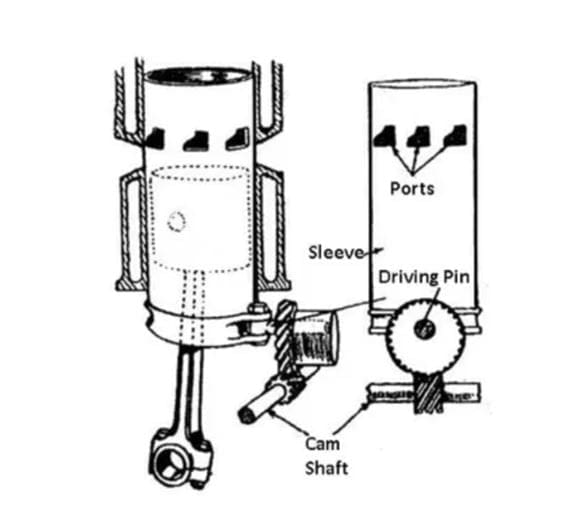
A sleeve valve consists of a sliding tube-like structure between the piston and the cylinder valve. This sleeve has two-day ports in it for inlet of fuel and outlet of exhaust gases and the same is the case with the cylinder.
The sleeve gets its vertical and rotational motion from the crankshaft of the engine.
Then the inlet port of the sleeve and the inlet port of the cylinder coincide the fuel enters the combustion chamber and when the exhaust port of the sleeve and exhaust port of the cylinder coincide, the exhaust gases vent out of the cylinder.
These types of valves have a simple construction and produce less noise.
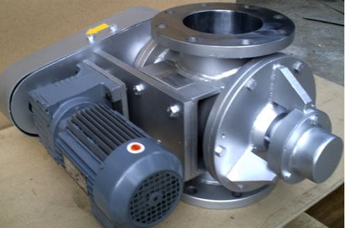
Rotary valve:
A rotary valve has a motor-like structure. It has four values for the inlet and outlet which are situated on the outer cylinder.
The inner shaft consists of a blade-like structure that is used to close and open the ports. The figure of a rotary value is given below.
Reed valve:
Reed valve is a whole different type of valve used in an internal combustion engine. It has ports that are covered by hinged metallic strips.
The reed valve is designed in such a way that the inlet pressure opens the inlet port for air and fuel and closes the exhaust port while the exhaust pressure opens the exhaust port and closes the inlet port.

Poppet valve:
The poppet valve is the most effective and widely used in internal combustion engines. The simple design makes it operational under various conditions.
The up-down motion of poppet valves is ideal for IC engines.
There are very few chances of fuel leaks in the case of poppet valves. The structure and details of the poppet valve are given below.
Structure or Parts of a Modern Engine Valve:
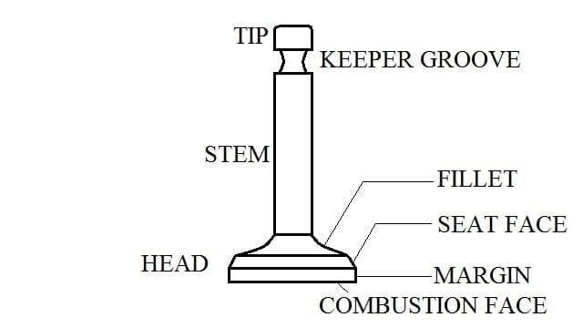
Nowadays the engine uses a poppet-type valve due to its up and down motion which closes and opens the valve respectively. The basic structure or a poppet valve is given below:
The valve structure is divided into two parts, the upper one is called the stem and the lower one is called the head.
The top of the stem is called a tip which is always in contact with the camshaft. Below the tip is provided with a keeper groove.
The head consists of a fillet which is designed according to the port of the engine. The fillet is followed by the seat face which fits into the port to block the flow of the substance.
Margin is the largest diameter of the valve and the combustion face is situated inside the cylinder which faces the combustion reactions inside the cylinder.
Types of Poppet valves based on the Fabrication technique:
Based on the fabrication of the valves the poppet valves are divided into 3 parts.
- Monometallic engine valve
- Bimetallic engine valve and
- Hollow engine valve
Monometallic engine valve:
As the name suggests a Monometallic engine valve is made up of similar material from stem to the head. They have high thermal resistance as well as great anti frictional qualities.
They have excellent metallic properties and are resistant to Corrosion. Chromium, manganese, stainless steel can be used for making these exhaust valves.
Bimetallic engine valve:
In a Bimetallic engine valve, the head and the stem are fabricated individually. And then they are welded by friction welding.
Generally, austenitic steel is used for the valve head and martensitic steel is used for the stem. The mechanical properties of each of These materials serve important purposes.
The austenitic steel offers Corrosion resistance and temperature resistance which is important for the conditions inside the cylinder block.
On the other hand, martensitic steel offers high resistance to wear and tensile loading.
Hollow engine valve:
The hollow engine valves are a special type of Bimetallic valve with a hollow cavity that is filled with Sodium metal. The Sodium metal starts converting into liquid when the temperature of the valve rises.
This allows a better heat transfer from the austenitic steelhead to the martensitic steel stem. And hence it is used in modern automobiles.
Working of an engine valve:
The following steps are following:
- At first, the power is given to the crankshaft of the engine.
- The crankshaft is used to run the camshaft of the engine.
- As the camshaft moves it pushes down the inlet valve during the suction stroke of the engine.
- As the piston follows the compression stroke the movement of the camshaft lets the inlet valve close because of its spring force.
- After the compression stroke, the piston follows a power stroke where both the valves remain closed.
- After the power stroke of the engine, there comes the exhaust stroke where the movement of the camshaft pushes the exhaust valve and opens it.
- The exhaust gases are pushed out by the piston and the cycle follows.
Valve Timing diagram:
The diagram which shows the correct timing of opening and closing of exhaust and inlet valves is called the valve timing diagram. A valve timing diagram is made concerning the movement of the piston inside the cylinder.
In a valve Timing diagram, the top of the circles or the 90 degrees concerning the x-axis is said to be the top dead centre or TDC. And bottom or 270 degrees concerning the x-axis represents the bottom dead centre or BDC.
Ideal or theoretical valve timing diagram:
The ideal valve timing diagram represents how the timing of the valve should sync with the piston movement.
- The inlet valve opens (IVO) when the piston is at the top dead centre.
- The piston then reaches the bottom dead centre, where the inlet valve closes (IVC).
- Then the piston follows the compression stroke where the fuel is compressed and burnt.
- As the fuel burns, it pushes the piston again to the bottom dead centre following the expansion or power stroke.
- When the piston reaches the bottom dead centre the exhaust valve is opened (EVO).
- The piston now follows the exhaust stroke where the piston pushes the exhaust gases out of the exhaust valve.
- When the piston reaches the top dead centre after the exhaust stroke the exhaust valve closes (EVC).
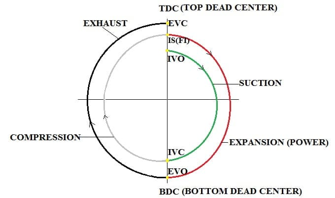
Actual valve timing diagram for 4 stroke petrol engine:
The actual valve timing diagram is different from that of the ideal or theoretical valve timing diagram.
- Suction Stroke
- Compression Stroke
- Expansion Stroke and
- Overlap
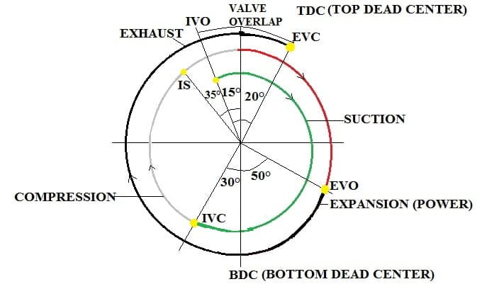
Suction stroke:
The suction stroke in the case of a four-stroke petrol engine starts about 15 degrees before the top dead centre when the pressure drops below the atmospheric pressure inside the cylinder.
This is when fresh charge enters the combustion chamber. When the piston reaches the bottom dead centre the ideal suction stroke is completed. But in this case, though the piston starts moving upwards the inlet valve remains open for about 30 degrees.
This helps in more inflow of the charge due to the ram effect. The inlet valve closes 30 after BDC. Hence the actual suction stroke is longer than the ideal suction stroke.
Compression stroke:
The compression stroke starts from 30 degrees after the BDC and continues till TDC where the ignition of the fuel is done with the help of a spark plug.
The actual compression stroke is 30 degrees less than the ideal compression stroke. During this stroke both the valves remain closed.
Expansion stoke:
Expansion or power stroke is the only useful stroke in a 4 stroke engine.
The burning of fuel pushes the piston down which helps in the movement of the flywheel. During the expansion stroke, both inlet and outlet valves are closed.
The expansion stroke ends around 50 degrees before the BDC.
Exhaust stroke:
The exhaust stroke in a 4 stroke petrol engine starts around 50 degrees before BDC where the exhaust valve is opened and continues 20 degrees after TDC when the exhaust valve is closed again.
This makes the exhaust stroke the longest stroke. During this stroke, the piston pushes the exhaust gases out of the exhaust valve.
Overlap:
There is a 40 to 45 degrees span where both inlet and exhaust valves are open. This is called overlap.
This time is shared with both suction and exhaust stroke. During overlap, the fuel coming inside the cylinder along with exhaust gases is pushed out of the cylinder through the exhaust valve.
This helps in better cleaning of the cylinder which is essential to keep the inner walls of the cylinder free from carbon deposits.
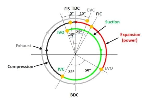
The actual Valve timing diagram for 4 Stroke diesel engine:
Suction stroke: In a four-stroke diesel engine, the inlet valve opens 25 degrees before TDC and allows the air to flow in suction stroke begins. The suction stroke continues till 25 degrees after BDC where the inlet valve closes.
Compression stroke: Compression stroke starts 25 degrees after BDC and continues till TDC. Here both the valves remain closed and fuel injection (diesel) starts 5 degrees before TDC.
Expansion stroke: The expansion stroke starts at TDC and the fuel injection stops 15 degrees after TDC. Here the fuel is burnt to the pressure applied by the piston. The expansion stroke continues till 50 degrees before BDC.
Exhaust stroke: The exhaust valve opens 50 degrees before the BDC and the exhaust emission takes place. The exhaust valve then closes 15 degrees after TDC.
Overlap: As in the previous case, there is a 35 to 40 degrees span for the internal cleaning of the engine.
Two Types of Valve Operating Mechanism:
The Engine valve is operated by a cam which is mounted on the camshaft. and It gets motion from the crankshaft. When the camshaft is on, the cam operates the valve. There are two types of valve mechanisms:
- Side Valve Mechanism (Straight Poppet Valve)
- Overhead Mechanism (Overhead Poppet Valve)
Side Valve Mechanism:
In this mechanism, the inlet valve is on the side of the cylinder valve. When the camshaft turns the cam, the lobe opens the valve directly through the tappet against the spring’s tension.
And when the cam lobe attains the maximum height, the valve opens completely.
Overhead Valve Mechanism:
The overhead-valve mechanism is placed on the overhead of the combustion chamber. When the camshaft turns, the cam lobe brings the tappet upward and when the tappet moves up, the valve pushes the push-rod and one end of the rocker arm upwards.
The other side of the rocker arm’s tip moves downward and the inlet valve opens against the spring’s tension. The valve opens fully when it When the cam lobe reaches the maximum height.
Further rotation of the camshaft causes the tappet to move down and the valve is closed by the tension of the spring.
Materials used for Making Engine valves:
The material used for making exhaust valves is different for both inlet and outlet valves. The basic requirements of engine valve material are that they should be temperature resistant, should have wear resistance, high tensile strength, and corrosion resistance.
But the inlet valve suffers comparatively less pressure and temperature when compared to the exhaust valve.
This is due to the fact that the fuel and air coming in from the inlet valve cools the inlet valve while the exhaust valve suffers heat generated due to the hot exhaust gases.
Due to the generation of low thermal stresses, the intake valve is made of materials such as chrome, tungsten, or nickel steel.
On the other side, the exhaust valves are made of high thermal resistive materials such as cobalt-chromium or silicon chromium alloys.
No comments:
Post a Comment